Very high frequency switching cell-based power converter

Inactive Publication Date: 2012-03-22
FINSIX
View PDF1 Cites 74 Cited by
  • Summary
  • Abstract
  • Description
  • Claims
  • Application Information

AI Technical Summary

Benefits of technology

[0085]In yet another aspect of the present invention, a VHF switching power converter is provided. The VHF switching power converter may include at least one power cell configured to receive an AC line input signal to provide an output suitable for powering an LED. Each of the at least one power cell may be separately controllable. Further, a portion of the at least one power cell may be arranged with parallel outputs. The VHF switching power converter may also include a controller for configuring the at least one power cell to receive the input signal and for facilitating switching the power converter at a frequency in excess of 5 MHz. In addition, the VHF switching power converter may include an output stage for receiving an output from the at least one power cell and for delivering a combined output to an LED.
[0086]In an embodiment, the VHF switching power converter may further include an output stage that may facilitate configuring a parallel output combination of the at least one power cell. The at least one power cell may include one or more switched capacitors. Further, the at least one power cell may include at least one switched capacitor and a DC/DC regulating converter. The DC/DC regulating converter may be disposed in series with the at least one switched capacitor. The controller soft switching of the at least one power cell. In an embodiment, the minimum efficiency threshold may be seventy percent, seventy-five percent, eighty percent, and the like. Further, the controlling the at least one power cell may include passive switched capacitor voltage balancing. The VHF switching power converter may operate above 5 MHz. In addition, powering the LED-based light may not require use of electrolytic capacitors.

Problems solved by technology

Present power converter systems require large and heavy capacitor banks to sustain transients demanded by the radar under transmit.
In each case, the existing power converter technology falls short of desired characteristics necessary to propel SSL lamps to commercial success.

Method used


Image

  • Very high frequency switching cell-based power converter
  • Very high frequency switching cell-based power converter
  • Very high frequency switching cell-based power converter

Examples


Example

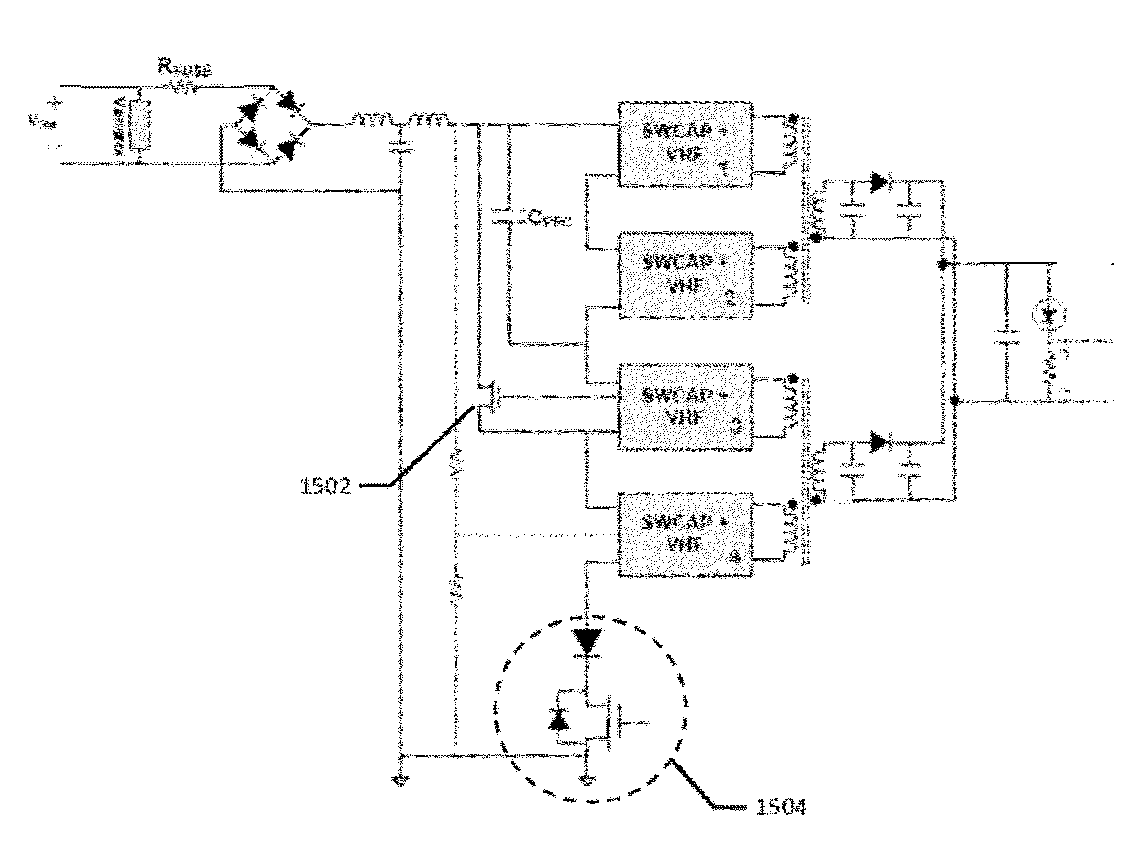
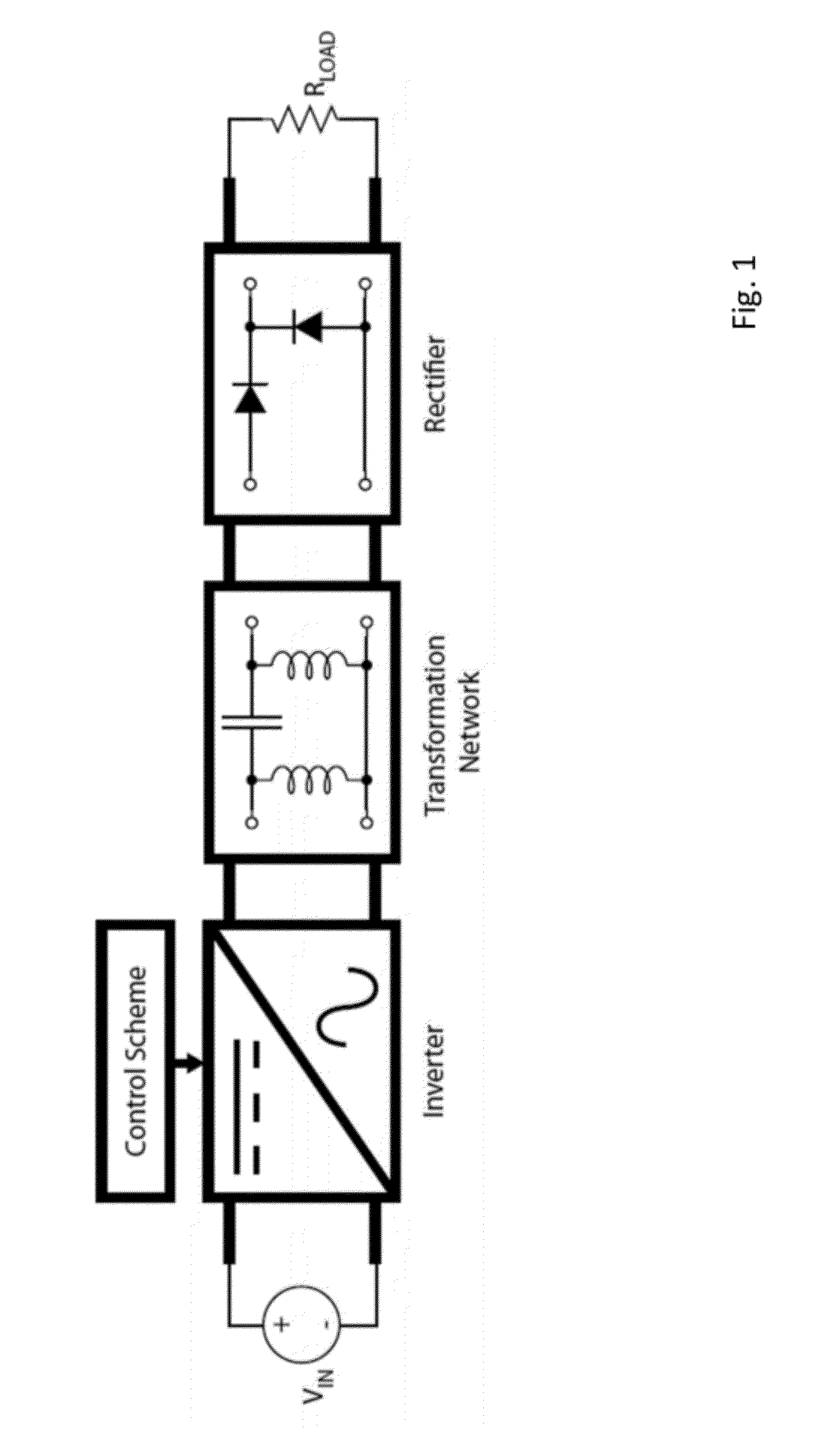
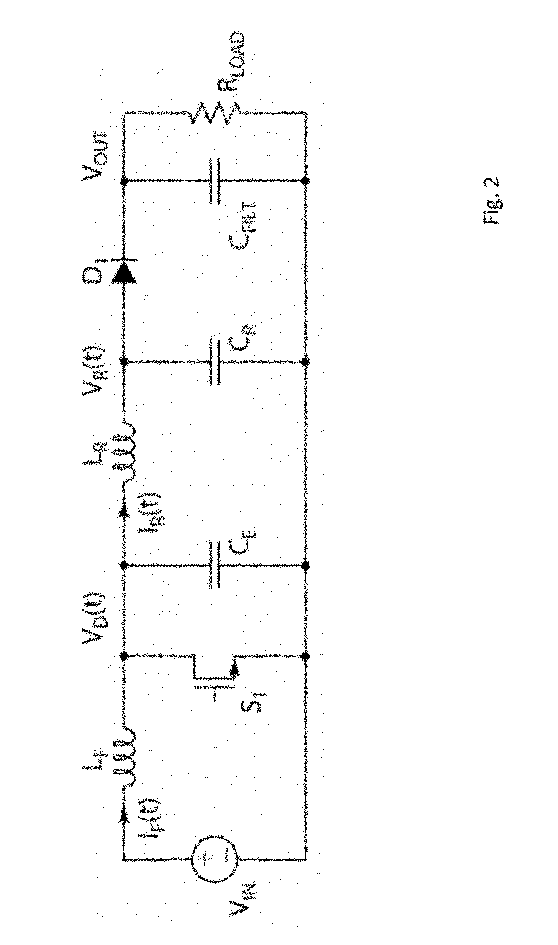
[0144]Increasing the switching frequency of a switched-mode power supply (SMPS) is a goal that is widely sought after as a means to increase power density and improve transient performance. However, increasing switching frequency using conventional power converter topologies (boost, buck, flyback, etc.) results with significantly degraded efficiency. Additionally, as switching frequency is increased, power density only increases until an optimal switching frequency is reached, at which point power density begins to decrease again. A new power converter architecture is described herein that breaks the bounds of conventional techniques, enabling efficient high frequency operation while delivering increased power per converter volume.

[0145]Soft-switched resonant inverters have been developed for high efficiency radio-frequency (RF) transmitter applications. These techniques have been adapted to form efficient DC / DC converters at switching frequencies greater than 100 MHz. The basic stru


PUM


Abstract

In an aspect, the present invention provides a high frequency switching power converter. The high frequency switching power converter may include a plurality of soft-switchable power cells flexibly connected to receive an input signal in series and provide an output. The high frequency switching power converter may further include a controller for configuring the flexible connection and for controlling the power cells to receive the input signal. In an embodiment, each of the plurality of power cells may be separately controllable by the controller. Further, a portion of the plurality of power cells may be arranged with parallel outputs. Additionally, at least one of the plurality of cells may include one or more switched capacitors. In another embodiment, the at least one of the plurality of cells may include at least one switched capacitor and a DC/DC regulating converter.

Description


Claims


Application Information

Patent Timeline
Owner FINSIX
Why Eureka
Try Eureka