Vaporizing Pipe Comprising Wire Coils

Inactive Publication Date: 2012-07-12
STEINBERG DAN
View PDF0 Cites 5 Cited by
  • Summary
  • Abstract
  • Description
  • Claims
  • Application Information

AI Technical Summary

Benefits of technology

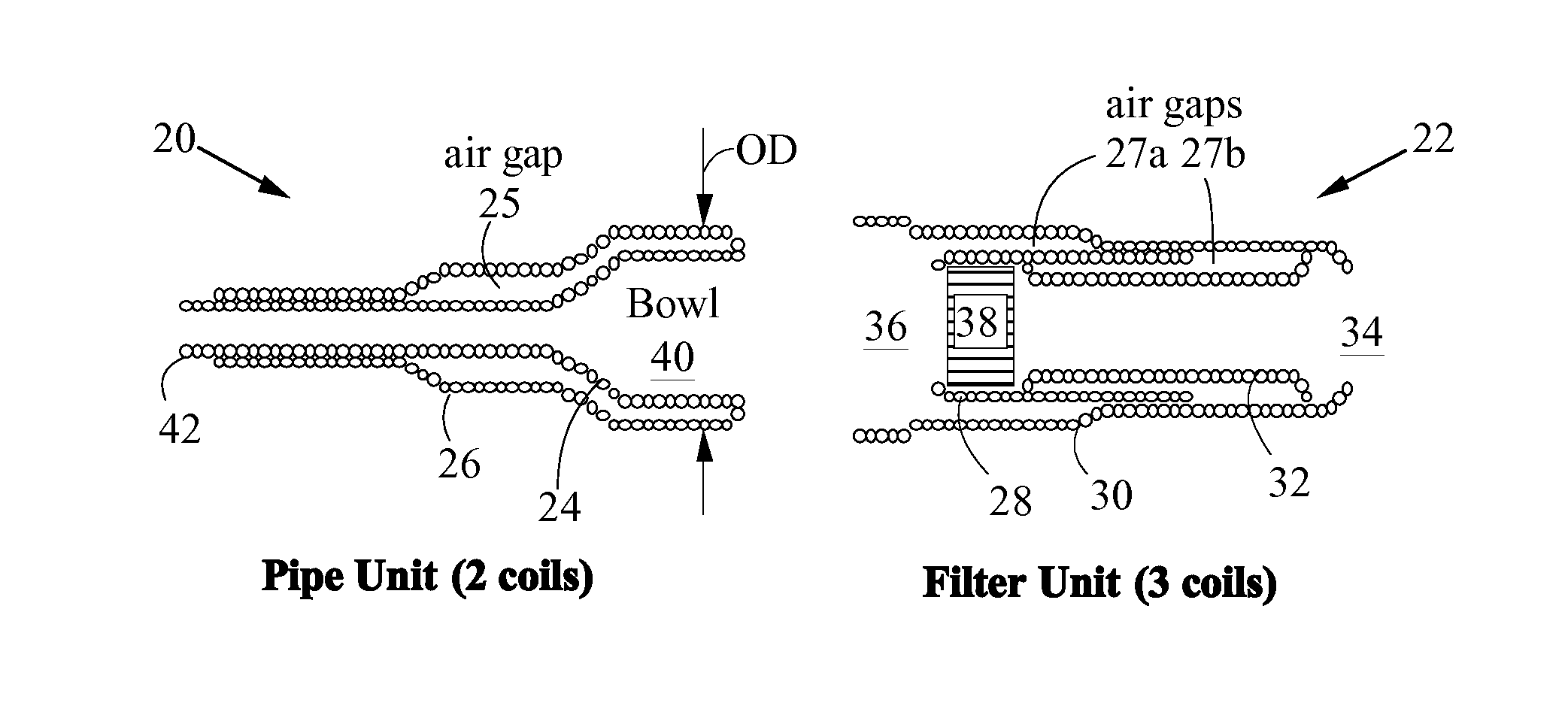
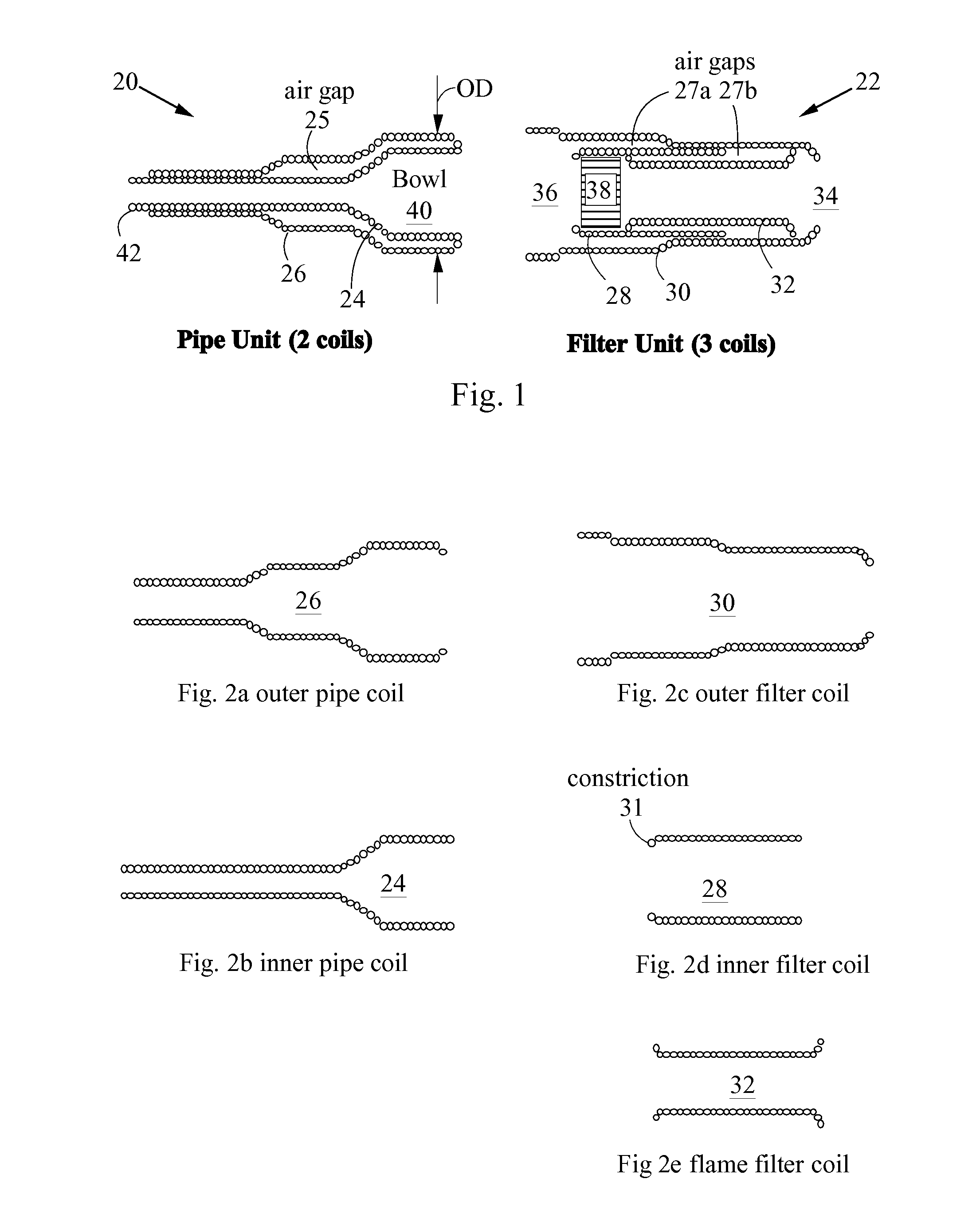
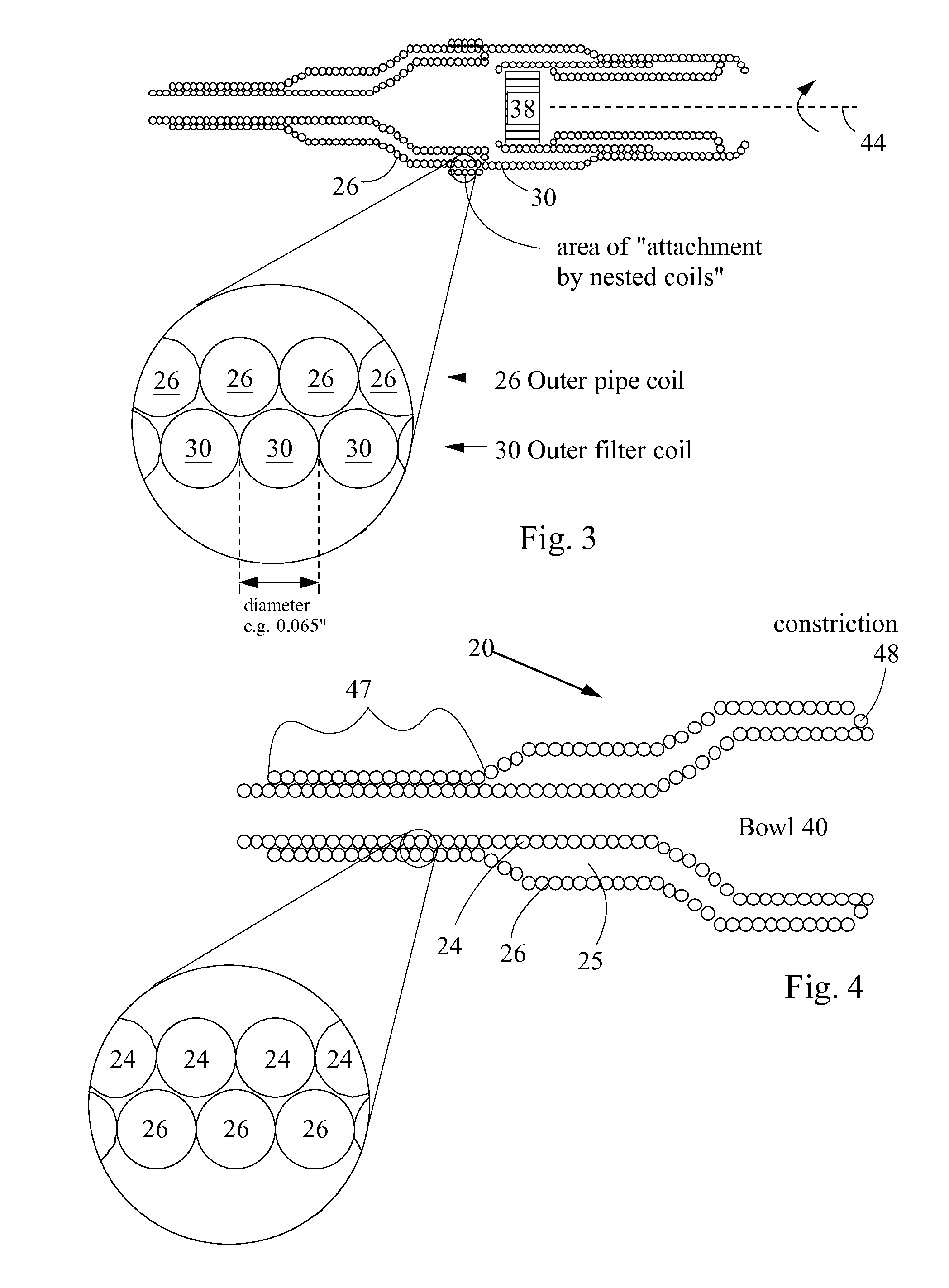
[0012]The vaporizing pipe can further comprise an outer pipe coil disposed around the pipe coil. The pipe coil and outer pipe coil can be attachable by nested coils. An air gap can be provided between the pipe coil and the outer pipe coil. Such an air gap provides excellent thermal insulation.

Problems solved by technology

Also, vaporization is smoother and more flavorful, and lacks the disagreeable burned taste produced by conventional smoking.
However, vaporization is difficult to perform, since vaporization only occurs in a relatively narrow temperature range.
A difficulty with vaporizing pipes is that, surprisingly, more heat can be required for vaporization compared to smoking This is because all the air drawn through a vaporizing pipe must be heated to vaporization temperature.
Consequently, a vaporizing pipe may become even hotter than a conventional smoking pipe.
The pipe can become too hot to hold, and can become so hot that it burns the user.
However, a disadvantage of wood is that it is difficult to clean.
Liquid cleaners (e.g. solvents, soap, alcohol) cannot be used.
Consequently, a wooden pipe will never be completely clean after it has been used once.
Also, wood can chip and crack; it is less durable than metal.
Consequently, metal pipes become excessively hot.
This is particularly a problem with aluminum vaporizing pipes.
Also, metal pipes machined from the highest quality materials (e.g. stainless steel, titanium) are very expensive to manufacture.

Method used


Image

  • Vaporizing Pipe Comprising Wire Coils
  • Vaporizing Pipe Comprising Wire Coils
  • Vaporizing Pipe Comprising Wire Coils

Examples


Example

[0029]The present invention provides a vaporizing pipe with improved manufacturability and performance and lower cost.

[0030]The present vaporizing pipe comprises a pipe unit and a filter unit. The pipe unit and filter unit each comprise at least one wound wire coil. The wire coils are wound so that they are approximately airtight (i.e. there is at most a small gap between some adjacent coils). Consequently, the wire coils are functionally equivalent to solid-walled tubes. The wire coils are attachable by nested coils. Attachment by nested coils is a natural consequence of making the coils with the same diameter wire because coils made with identical wire have the same “thread pitch”. Also, additional outer wire coils can be provided on both the pipe unit and filter unit. The inner and outer coils can be designed to create air gaps, thereby providing excellent thermal insulation. The present vaporizing pipe can be made of stainless steel at low cost and can be cleaned with liquid cleane


PUM


Abstract

Provided is a vaporizing pipe made from wound wire coils. The vaporizing pipe comprises two halves: a pipe unit and a filter unit. The pipe unit has a bowl for holding smoking material. The filter unit contains a flame filter for providing vaporization temperatures, as known in the art. The pipe unit and filter unit attach by twisting/rotating (“attachment by nested coils”). The windings of the coils screw together in a manner similar to screw threads. The pipe unit can comprise 1, 2 or more coils. The filter unit can comprise 1, 2, 3 or more coils. Air gaps can be disposed between coils, thereby providing thermal insulation. The coils can be made of stainless steel wire for example. The wire can have a diameter of about 0.050-0.075 inches for example.

Description


Claims


Application Information

Patent Timeline
Owner STEINBERG DAN
Why Eureka
Try Eureka