Methods, systems and apparatus for the interconnection of fibre channel over ethernet devices
- Summary
- Abstract
- Description
- Claims
- Application Information
AI Technical Summary
Benefits of technology
Problems solved by technology
Method used
Image

Examples
Example
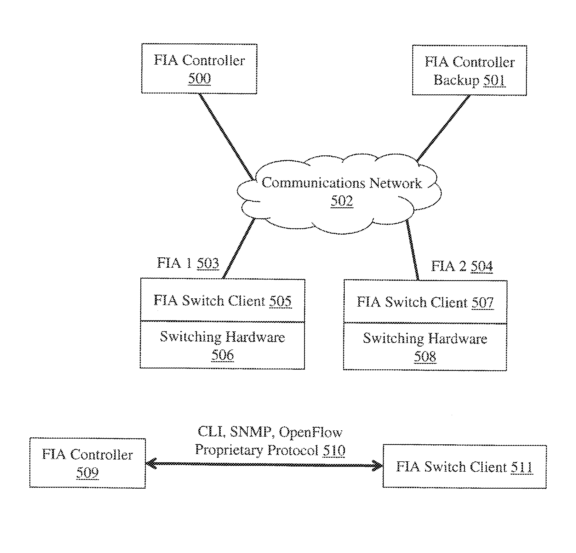
ACRONYMS
[0063]ACE Access Control Entry[0064]ACL Access Control List[0065]ACLE Access Control List Entry[0066]BPDU Bridge PDU[0067]CNA Converged Network Adapter[0068]DA Destination Address[0069]DCB Data Center Bridging[0070]DCBX DCB Exchange protocol[0071]EISS Extended Internal Sublayer Service[0072]ENode FCoE Node[0073]ETS Enhanced Transmission Selection (IEEE 802.1Qaz)[0074]FC-MAP FCoE Mapped Address Prefix[0075]FCF FCoE Forwarder[0076]FIA FCoE device and Fibre Channel node interconnection Apparatus[0077]FCF-MAC FCoE Forwarder Media Access Control[0078]FCID Fibre Channel address or port identifier[0079]FCoE Fibre Channel over Ethernet[0080]FCoE Device Another term for ENode[0081]FCoE_LEP FCoE Link Endpoint[0082]FDF FCoE Data Forwarder[0083]Fibre Channel device Another term for Fibre Channel node[0084]RP FCoE Initialization Protocol[0085]FME Frame Match Entry[0086]FPMA Fabric Provided MAC Address[0087]IEEE Institute of Electrical and Electronics Engineers[0088]IP Internet Protocol[0089
PUM
 Abstract
Description
Claims
Application Information
 - R&D Engineer
- R&D Manager
- IP Professional
- Industry Leading Data Capabilities
- Powerful AI technology
- Patent DNA Extraction
Browse by: Latest US Patents, China's latest patents, Technical Efficacy Thesaurus, Application Domain, Technology Topic.
© 2024 PatSnap. All rights reserved.Legal|Privacy policy|Modern Slavery Act Transparency Statement|Sitemap