Water treatment system

a water treatment system and water treatment technology, applied in multi-stage water/sewage treatment, water/sewage treatment by oxidation, operating means/releasing devices of valves, etc., can solve the problems of low water pressure profile created by manual pumps, erratic, etc., and achieve high flow rate, substantial effect of filtration stage and high performan

Inactive Publication Date: 2012-07-26
ACCESS BUSINESS GRP INT LLC
View PDF9 Cites 12 Cited by
  • Summary
  • Abstract
  • Description
  • Claims
  • Application Information

AI Technical Summary

Benefits of technology

This patent describes a device called a hand-pump for water treatment systems. It uses a manually operated pump to monitor the amount of water being treated. When there are no more water, it generates enough power to operate the pump. However, when there's too much water, the pump stops working properly. To prevent this problem, the device has two modes: 1. Active mode: During normal operation, the pump works on its own, generating power only during certain times. By activating the pump at specific times, users can measure how many water they want to drink. These measurements can then be stored temporarily until needed again. 2. Automate Exposure Mode: Unlike traditional methods like pumps, these devices automatically move water into different areas based on their needs. They generate power continuously but slowly, allowing them to monitor the amount of water used effectively. Additionally, the device includes a mechanism to control the pump's movement back and forth. Users can adjust the pump's position to increase or decrease the amount of water they require. Overall, these technical features improve the efficiency and accuracy of water treatment systems.

Problems solved by technology

The technical problem addressed by this patent is how to create a small and portable household POD system for individuals without access to regular public supplies like drinking water, which can help them save money on purchasing expensive equipment.

Method used


Image

  • Water treatment system
  • Water treatment system
  • Water treatment system

Examples


Embodiment Construction

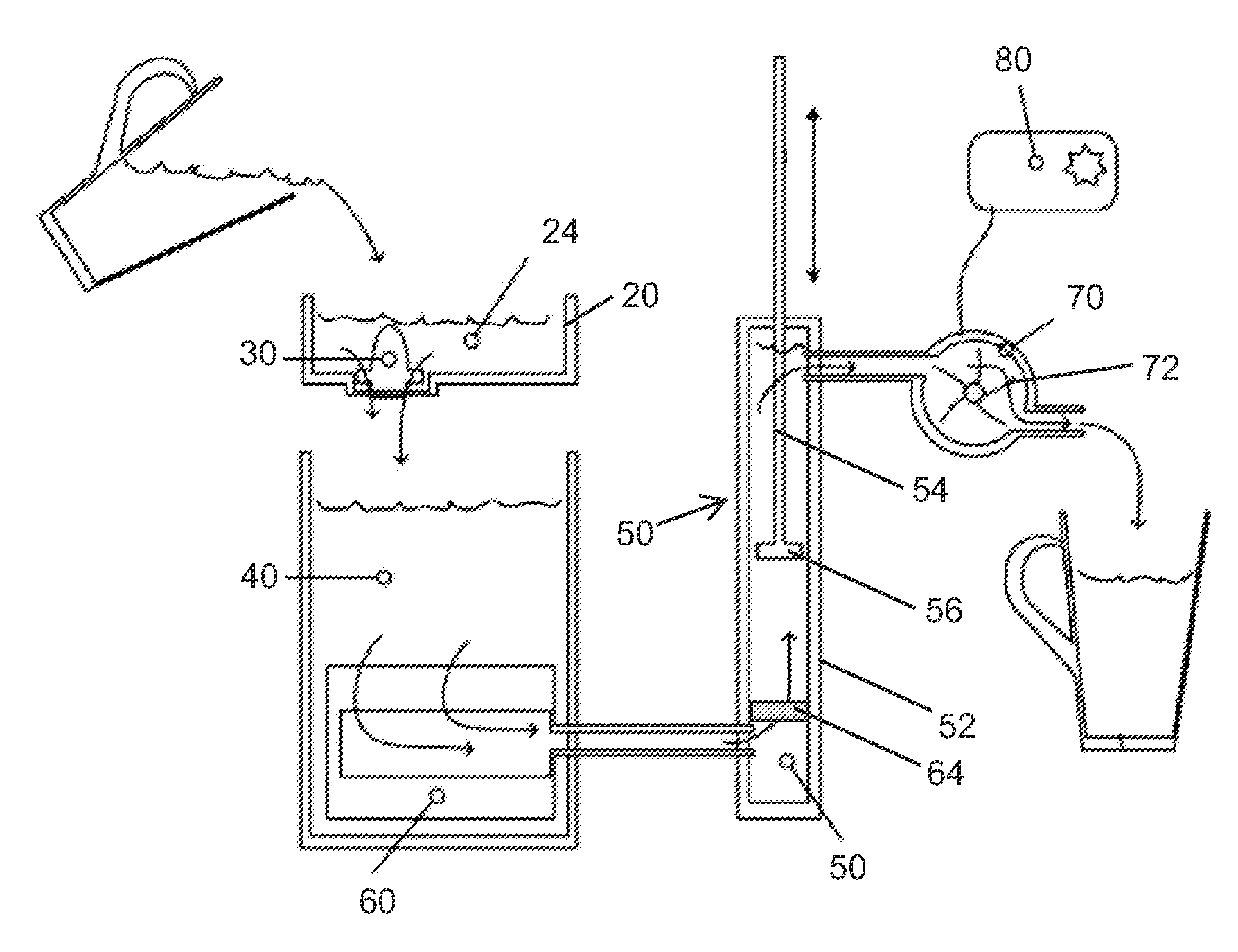
[0021]Referring to FIG. 1, one embodiment of a flow path through a water treatment system is illustrated. Water can be added to the system as desired. For example, water may be added at the time of desired consumption or may be added in anticipation of consuming the water at a later time. Although the current embodiment is a water treatment system, it should be understood that the system could be utilized for treating essentially any liquid. In the current embodiment, the water treatment system is designed to accept non-potable water that can benefit from chemical disinfection, such as chlorination, and filtration. Once water is added to the inlet 20, the water passes through the chemical disinfection doser 30. The chemical disinfection doser 30 can be a variety of different shapes and sizes. The chemical disinfection doser 30 in the current embodiment is a chlorinator. One embodiment of a chlorinator 30 capable of being utilized in the current embodiment is illustrated in FIG. 6, and


PUM


Abstract

A water treatment system is provided including a disinfection system, a filter and a turbine generator. A manual pump is positioned downstream of the filter to create negative pressure to draw water through the filter. The manual pump also creates positive pressure to dispense treated water from the outlet of the system. The movement of the water through the system powers the turbine generator. The power generated can be used to monitor a characteristic of the water treatment system.

Description


Claims


Application Information

Patent Timeline
Owner ACCESS BUSINESS GRP INT LLC
Why Eureka
Try Eureka