Adhesiveless decorative floor tile

Inactive Publication Date: 2012-12-27
GROWLIFE INC
View PDF2 Cites 13 Cited by
  • Summary
  • Abstract
  • Description
  • Claims
  • Application Information

AI Technical Summary

Benefits of technology

[0004]The present invention provides an adhesiveless decorative floor tile that includes at least one decorative layer and a backing layer. An array of resilient annular projections are located on an outer surface of the backing layer. Each annular projection defines a blind passageway arranged so that when pressure is applied to the decorative layer, a partial vacuum is formed within each

Problems solved by technology

Flooring products often stay in place during use, and can be subjected to walking forces, dragging forces, rolling load forces, indentation forces, and sub-floor movement due to dimensional instability.
However, none of these tile technologies have had significant commercial success.
While this approach provides acceptable

Method used


Image

  • Adhesiveless decorative floor tile
  • Adhesiveless decorative floor tile
  • Adhesiveless decorative floor tile

Examples


Embodiment Construction

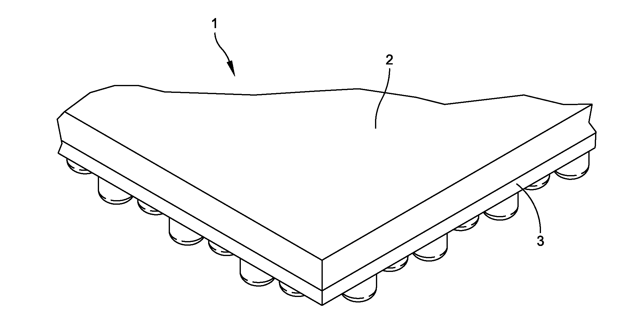
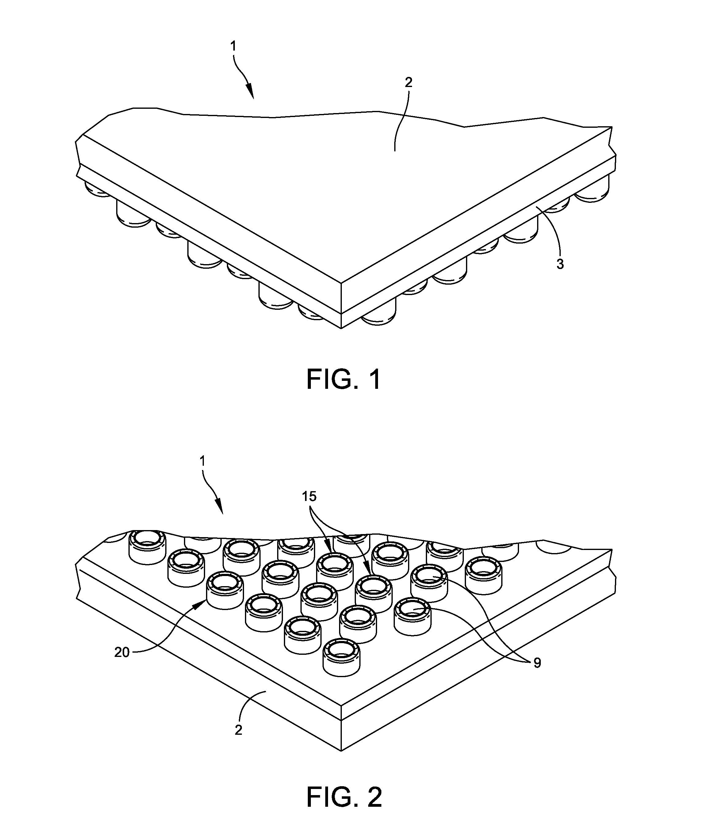
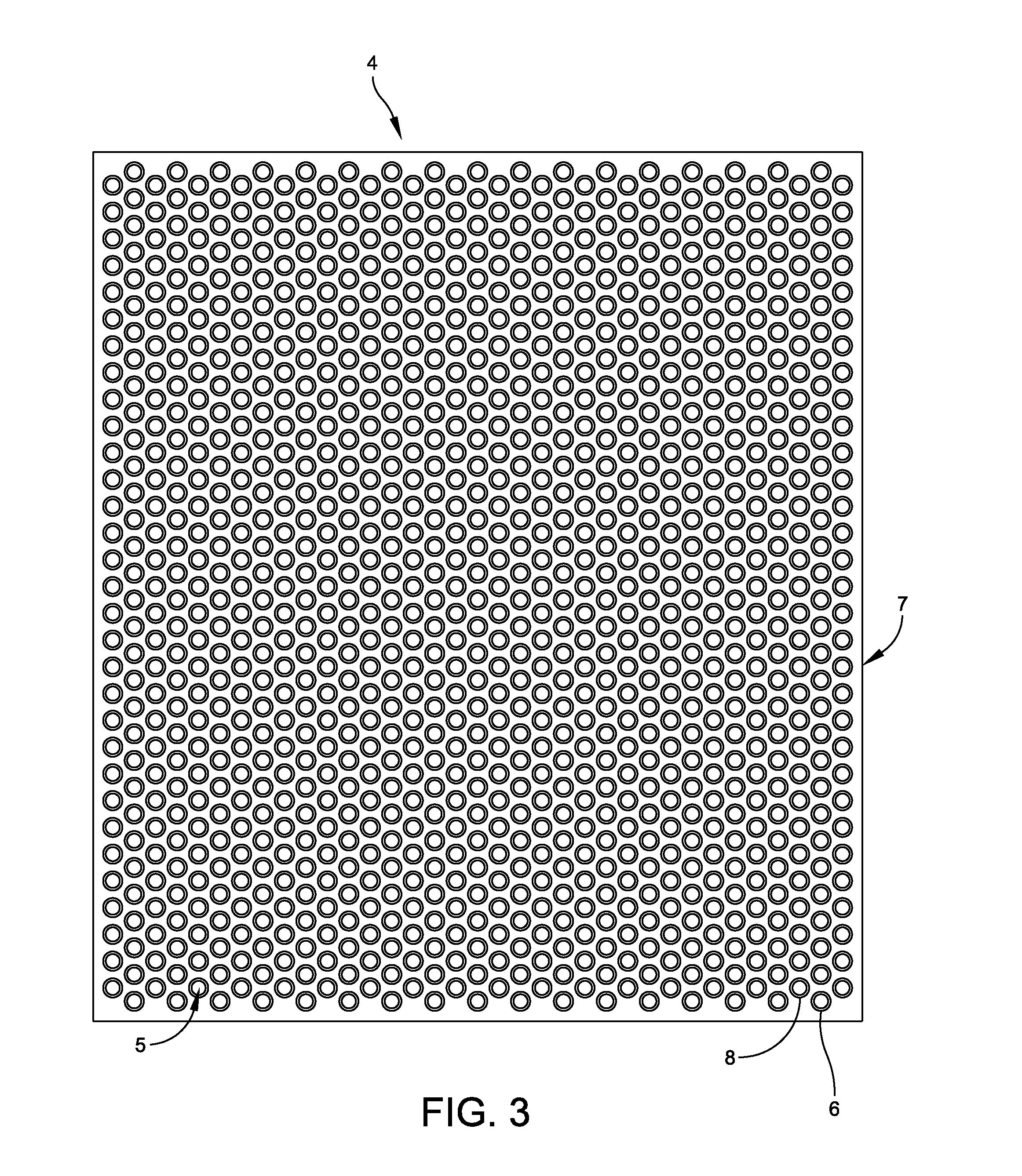
[0011]In one preferred embodiment of the invention, a decorative floor tile includes at least one decorative layer and a backing layer comprising an array of resilient annular projections, wherein each annular projection comprises a concave exposed top surface, an outside wall surface and an inside wall surface. The inside wall surface defines a blind passageway within the projection. When the decorative floor tile is installed over an underlying surface, and pressure is applied to the decorative floor tile, a vacuum is created within the blind passageway of the projections which adheres the floor tile to the underlying surface. The vacuum increases the amount of frictional drag between the tile and the underlying surface, and thus allows the tile to remain in place without the need for an adhesive.

[0012]Referring to FIGS. 1 and 2, a decorative floor tile 1 formed in accordance with one embodiment of the invention includes a decorative layer 2, e.g., a 15.3 cm×91.5 cm, Luxury Vinyl Til


PUM


Abstract

A decorative floor tile including at least one decorative layer and a backing layer having an array of resilient annular projections. Each annular projection includes a concave top surface, an outside wall surface, and an inside wall surface. The inside wall surface defines a central, blind passageway area. When the decorative floor tile is installed over an underlying surface, and pressure is applied to the decorative floor tile, a vacuum is created within the blind passageway and the underlying surface. The vacuum increases the amount of frictional drag between the surface covering and the underlying surface, and thus allows the surface covering to remain in place without the need for an adhesive.

Description


Claims


Application Information

Patent Timeline
Owner GROWLIFE INC
Why Eureka
Try Eureka