Device and method for driving liquid discharge head, liquid discharge apparatus, and ink-jet apparatus
a liquid discharge head and liquid discharge technology, which is applied in the direction of printing, inking apparatus, other printing apparatus, etc., can solve the problems of lowering the productivity of printers, difficulty in matching the droplet speed between different ink drops, and inability to form high-quality images, etc., to achieve improved droplet landing position accuracy, high picture quality, and high productivity
- Summary
- Abstract
- Description
- Claims
- Application Information
AI Technical Summary
Benefits of technology
Problems solved by technology
Method used
Image

Examples
modified example 1
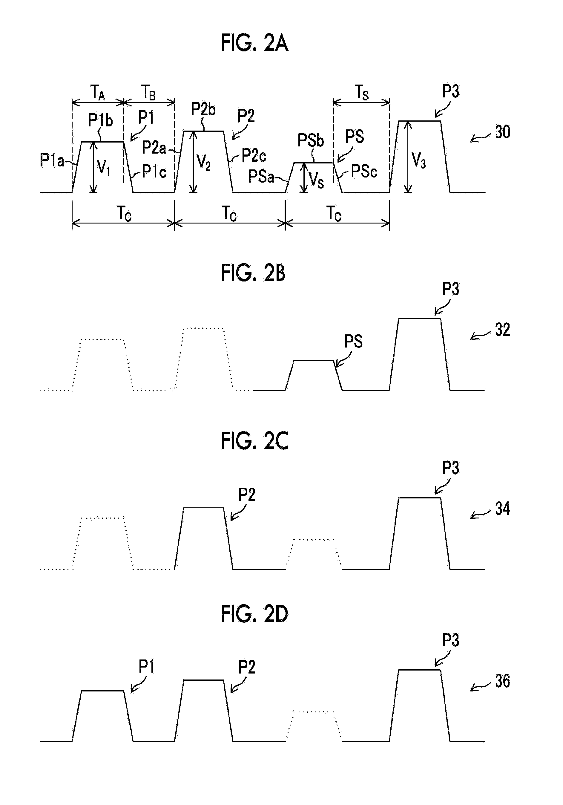
[0080]It is also possible to provide a configuration that adds a reverberation restraint pulse (which may be called a meniscus correction unit or a reverberation restraint unit) for restraining the reverberation of the meniscus after discharging just after the last jet pulse P3 in the basic driving waveform 30 illustrated in FIG. 2A. In this case, the reverberation restraint pulse can be added to the driving waveform for discharging each of the droplets of the small droplet, the medium droplet, and the large droplet.
[0081]By combining the reverberation restraint pulse, the discharge efficiency of the last pulse can be further improved, and the meniscus vibration (reverberation) after discharging one recording period can be reduced to be able to seek the stabilization of consecutive recording.
modified example 2
[0082]Although it is exemplified that the driving waveforms illustrated in FIGS. 2A to 2D are configured to draw the meniscus into the pressure chamber direction through making the pressure chamber expand by a rising portion of the pulse to raise the voltage in the plus direction from the reference potential, it is also possible to adopt a configuration which performs a “pulling” operation for drawing the meniscus through making the pressure chamber expand by a falling portion of the pulse that lowers the voltage from the reference potential, and performs a “pushing” operation through contracting the pressure chamber by a rising portion to raise the voltage from the lowered voltage.
[0083]Regarding Kinds of Droplet Sizes
[0084]Although it has been described that three kinds of droplets, that is, the small, medium, and large droplets, are provided, the kinds of droplets can be generalized as follows. That is, it is possible to perform discharge with different droplet quantities by selecti
PUM
 Abstract
Description
Claims
Application Information
 - R&D Engineer
- R&D Manager
- IP Professional
- Industry Leading Data Capabilities
- Powerful AI technology
- Patent DNA Extraction
Browse by: Latest US Patents, China's latest patents, Technical Efficacy Thesaurus, Application Domain, Technology Topic.
© 2024 PatSnap. All rights reserved.Legal|Privacy policy|Modern Slavery Act Transparency Statement|Sitemap