Multilayered inductor and method of manufacturing the same

a technology of inductance and multilayer, applied in the direction of inductance, magnets, magnetic bodies, etc., can solve the problems of large change in inductance value according to current application, large impact on multilayered power inductance, etc., to improve an inductance value change and high capacitance

Inactive Publication Date: 2013-06-13
SAMSUNG ELECTRO MECHANICS CO LTD
View PDF7 Cites 17 Cited by
  • Summary
  • Abstract
  • Description
  • Claims
  • Application Information

AI Technical Summary

Benefits of technology

The present invention relates to a type of inductor that has multiple layers with different materials inside it. This allows for more efficient use of space while maintaining good electrical performance.

Problems solved by technology

This patent describes different technical problem addressed in the patent text relating to reducing size and increasing capacity of electronic devices while maintaining their performance. These issues include electrical interference caused by external sources, including radio frequency signals from nearby communication networks, and changes in inductance due to changes in voltage applied across terminals during use. To address these concerns, the patent proposes various techniques involving incorporation of a nonmagnetic gap layer between certain ceramics within the inductor's inner structure.

Method used


Image

  • Multilayered inductor and method of manufacturing the same
  • Multilayered inductor and method of manufacturing the same
  • Multilayered inductor and method of manufacturing the same

Examples


Embodiment Construction

[0035]Embodiments of the present invention will now be described in detail with reference to the accompanying drawings.

[0036]The invention may, however, be implemented in many different forms and should not be construed as being limited to the embodiments set forth herein.

[0037]Rather, these embodiments are provided so that this disclosure will be thorough and complete, and will fully convey the concept of the invention to those skilled in the art.

[0038]In the drawings, the shapes and dimensions may be exaggerated for clarity, and the same reference numerals will be used throughout to designate the same or like components.

[0039]In addition, like reference numerals denote parts performing similar functions and actions throughout the drawings.

[0040]In addition, unless explicitly described otherwise, “comprising” any components will be understood to imply the inclusion of other components but not the exclusion of any other components.

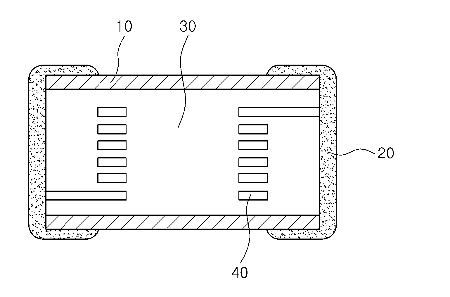
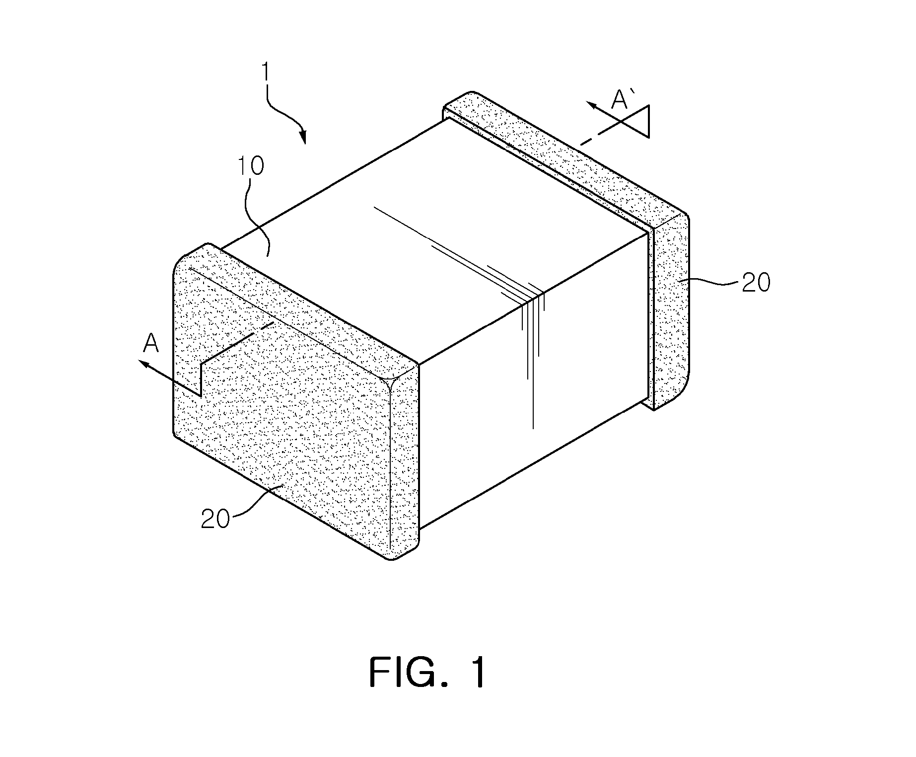
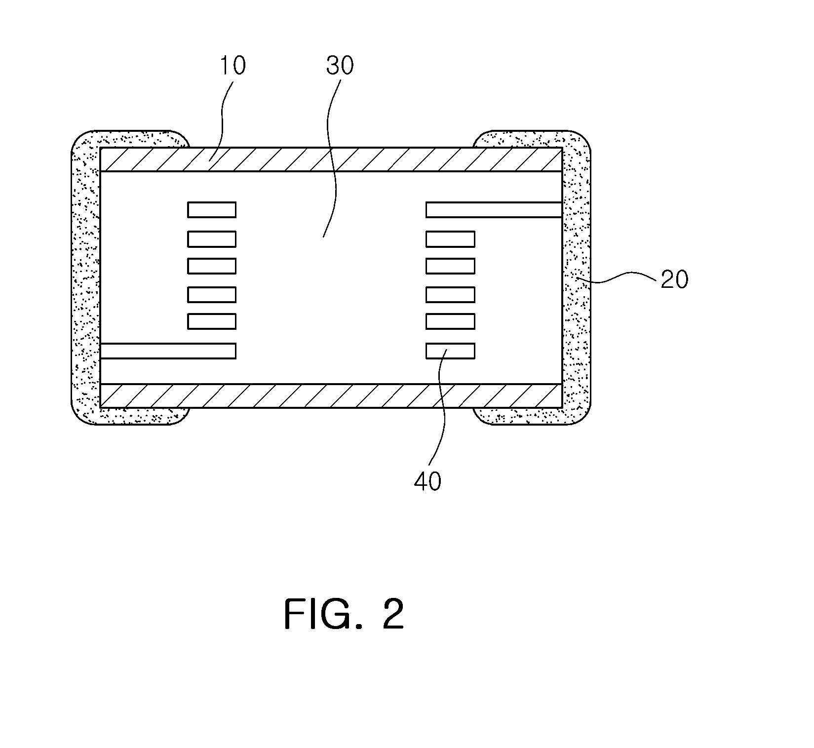
[0041]Referring to FIGS. 1 and 2, a multilayered induct


PUM

PropertyMeasurementUnit
Fractionaaaaaaaaaa
Electrical conductoraaaaaaaaaa
Magnetizationaaaaaaaaaa

Abstract

There is provided a multilayered inductor, including: an inductor body; a coil part formed on the inductor body and having a conductive circuit and a conductive via; and external electrodes formed on both end surfaces of the inductor body, wherein the inductor body includes 65 to 95 wt % of a metallic magnetic material and 5 to 35 wt % of an organic material.

Description


Claims


Application Information

Patent Timeline
Owner SAMSUNG ELECTRO MECHANICS CO LTD
Why Eureka
Try Eureka