Electronic Device and Method for Setting Time of Timer
a timer and electronic technology, applied in the field of electronic devices, can solve the problems of increased battery consumption and user discomfort, and achieve the effect of efficiently setting the time of the timer and freeing users from troubl
- Summary
- Abstract
- Description
- Claims
- Application Information
AI Technical Summary
Benefits of technology
Problems solved by technology
Method used
Image


Examples
first example
The First Example
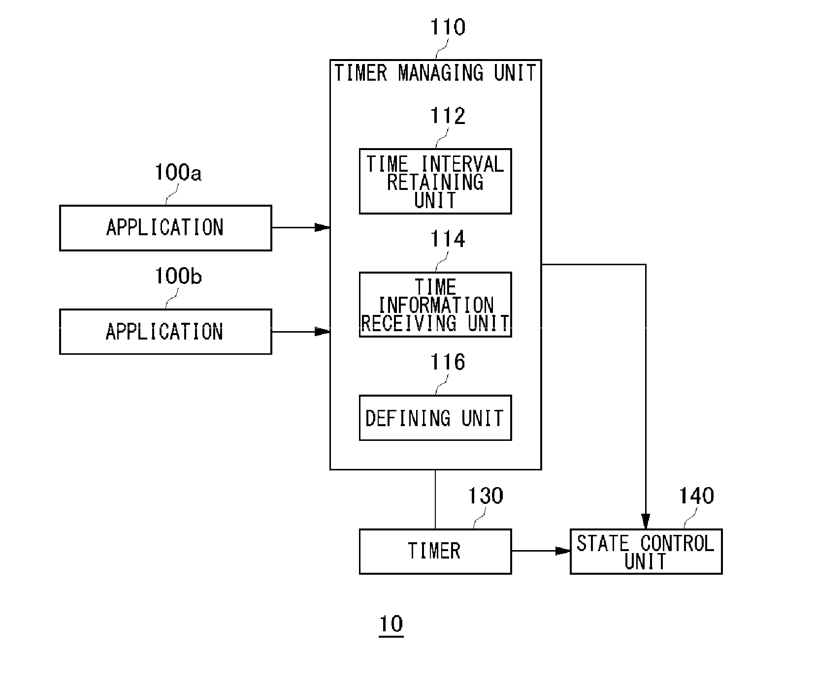
[0060]Here, it is assumed that the time interval T retained by the time interval retaining unit 112 is 15 minutes, the time information Ta is 30 minutes, and the time information Tb is 15 minutes. If T≧Ta or T≧Tb, the defining unit 116 determines the next set time of the initial set time as Tini+T. That is, if either one of the time intervals Ta and Tb for activation required by the applications 100 is less than or equal to the minimum time interval T for resume process, a set time is registered with the timer 130 for each time interval T, and the state control unit 140 executes the resume process at time interval T. Thereby the requests from the applications 100 can be satisfied.
[0061]In this example, T=15 minutes, and Tb=15 minutes. Therefore, T≧Tb and the next set time is determined as Tini+T. In this manner, the timer managing unit 110 according to the exemplary embodiment, even if just one application 100 with T≧Tb exists, the defining unit 116 determines the set
second example
The Second Example
[0064]Next, an explanation will be given on a case where T116 sometimes determines the set time as a time point calculated by adding a value of the time interval T multiplied by N (where N is a positive integer more than 1) to the last set time in case that all of the time information received from respective applications is larger than the time interval T. In the light of T116 determines that system resumes for each time interval T is not required, and derives time cycles for activation for respective applications 100. More specifically, the defining unit 116 determines the minimum P and Q (where P and Q are positive integers) that satisfy T times P≧Ta, and T times Q≧Tb, and recognizes that system resumes are sufficiently applied with a time interval of T times P for application 100a, and with a time interval of T times Q for application 100b. In this case, P=2, and Q=4 are required. Therefore, it is derived that system resumes are sufficiently applied with a time in
third example
The Third Example
[0068]Although in the second example, Q is an integral multiple of P, an explanation will be given on a case where T116 determines the set time subsequent to the time Tini as a time point calculated by adding a value of the time interval T multiplied by N (where N is a positive integer more than 1) to the time Tini because all of the time information received from respective applications is larger than the time interval T.
[0069]In this process, on the basis of T116 determines that system resumes at every T are not required, and derives timings to activate an application for respective applications 100. More specifically, the defining unit 116 determines the minimum P and Q (where P and Q are positive integers) that satisfy T times P≧Ta, and T times Q≧Tb, and recognizes that system resumes are sufficiently applied with a time interval of T times P for application 100a, and with a time interval of T times Q for application 100b. In this case, P=2, and Q=3 are required. T
PUM
 Abstract
Description
Claims
Application Information
 - R&D Engineer
- R&D Manager
- IP Professional
- Industry Leading Data Capabilities
- Powerful AI technology
- Patent DNA Extraction
Browse by: Latest US Patents, China's latest patents, Technical Efficacy Thesaurus, Application Domain, Technology Topic.
© 2024 PatSnap. All rights reserved.Legal|Privacy policy|Modern Slavery Act Transparency Statement|Sitemap