Textile arrangement and method for manufacturing

a technology of textiles and fabrics, applied in the direction of printed circuit aspects, sports equipment, trousers, etc., can solve the problems of difficult implementation of reliable and miniature joint and connection techniques for detachable electronic components, slow sewing of electrically-conducting cables or wires into textiles or garments, and inability to meet the requirements of high-speed, reliable and cost-effective manufacturing process

Inactive Publication Date: 2013-06-27
CLOTHING PLUS MBU
View PDF5 Cites 43 Cited by
  • Summary
  • Abstract
  • Description
  • Claims
  • Application Information

AI Technical Summary

Benefits of technology

This patented technology allows multiple circuits on different parts of clothes together without affecting them' overall appearance. It also provides mechanical strength while still being able to work well under severe conditions that could damage these devices. Additionally, this design makes sure they are secure during use by guiding small electric currents accurately through specific areas within the fabric itself.

Problems solved by technology

This technical problem addressed in this patents describes how current techniques used to integrate electronics onto fabrics can lead to slower operation times and less accurate guiding than desired. Additionally, existing solutions require complicated connections that cannot protect against environmental factors like moisture and dirt.

Method used


Image

  • Textile arrangement and method for manufacturing
  • Textile arrangement and method for manufacturing
  • Textile arrangement and method for manufacturing

Examples


Embodiment Construction

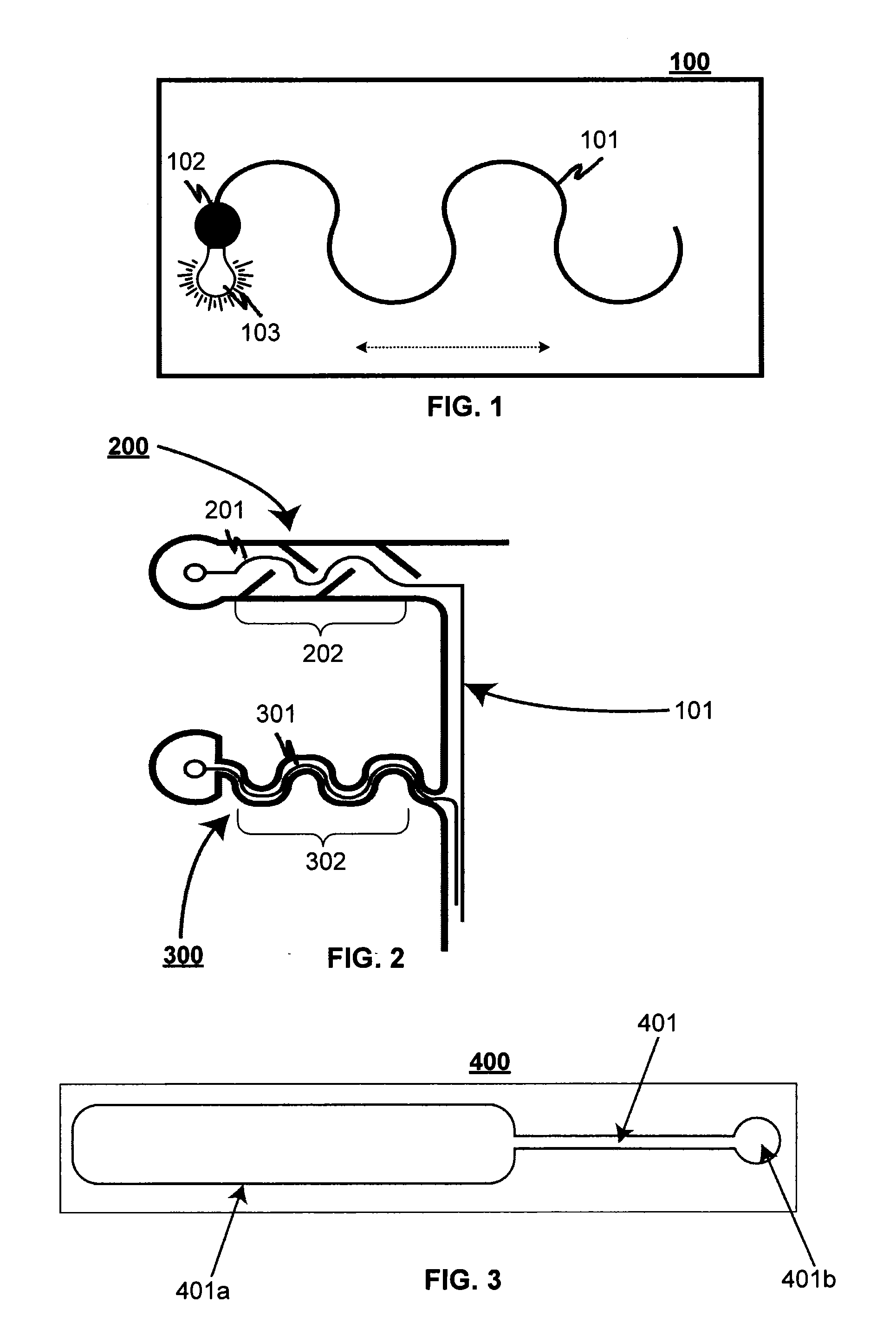
[0026]FIG. 1 illustrates an exemplary circuit board 100 with an electrically-conducting trace 101 according to an advantageous embodiment of the invention, where said circuit board is made of flexible and / or tensile substrate material and can thereby bend and / or stretch at least in one direction. The other end of the electrically-conducting trace is formed as a joint or pad 102, where a fixedly-integrated electronic component 103 is connected into the circuit board.

[0027]The electrically-conducting trace 101 is corrugated so that when the circuit board is bent and / or stretched, e.g., in the direction of the arrow, the corrugated trace 101 will be straightened out especially in the direction of the arrow, thereby allowing the trace to bend or stretch together with the circuit board without breaking, perishing or getting cut off.

[0028]FIG. 2 illustrates examples of flexible circuit boards 200, 300 with electrically-conducting traces according to an advantageous embodiment of the in


PUM

PropertyMeasurementUnit
Thicknessaaaaaaaaaa
Electrical conductivityaaaaaaaaaa
Tensile propertiesaaaaaaaaaa

Abstract

A textile arrangement that includes at least one flexible circuit board integrated with a textile and a fixedly-integrated electronic component in the flexible circuit board. The flexible circuit board includes a flexible and/or tensile substrate, which is configured to bend and/or stretch at least in one direction. In addition, the flexible circuit board includes at least one electrically-conducting trace, at least one end of the trace being coupled with the component. The electrically-conducting trace is configured to bend and/or stretch with the flexible and/or tensile substrate of the circuit board at least in said one direction, when the circuit board is bent and/or stretched.

Description


Claims


Application Information

Patent Timeline
Owner CLOTHING PLUS MBU
Why Eureka
Try Eureka