Self-compensating filament tension control device with eddy current braking

a tension control device and self-compensation technology, applied in the direction of filament handling, thin material processing, transportation and packaging, etc., can solve the problems of unfavorable use of tension control devices, and often multiple individual adjustments of creels having variable tension control

Active Publication Date: 2013-07-25
RJS
View PDF0 Cites 0 Cited by
  • Summary
  • Abstract
  • Description
  • Claims
  • Application Information

AI Technical Summary

Benefits of technology

The technical effect of this patented technology is that there are two aspects: one is how to prevent damage caused by excessive tensile stress on filaments during production or use; another is how to adjust the amount of filament being pulled out of a spooled material without causing damage.

Problems solved by technology

The technical problem addressed in this patent is how to design a tension control device that effectively controls the tension of a thread without imparting excessive forces onto the filament or the spool itself. Existing solutions involve using a separate spool carrying the filament or spun fiber, but they suffer from issues like imposition of torque due to gravity and lack of sufficient tightness between the spool and the spool.

Method used


Image

  • Self-compensating filament tension control device with eddy current braking
  • Self-compensating filament tension control device with eddy current braking
  • Self-compensating filament tension control device with eddy current braking

Examples


Embodiment Construction

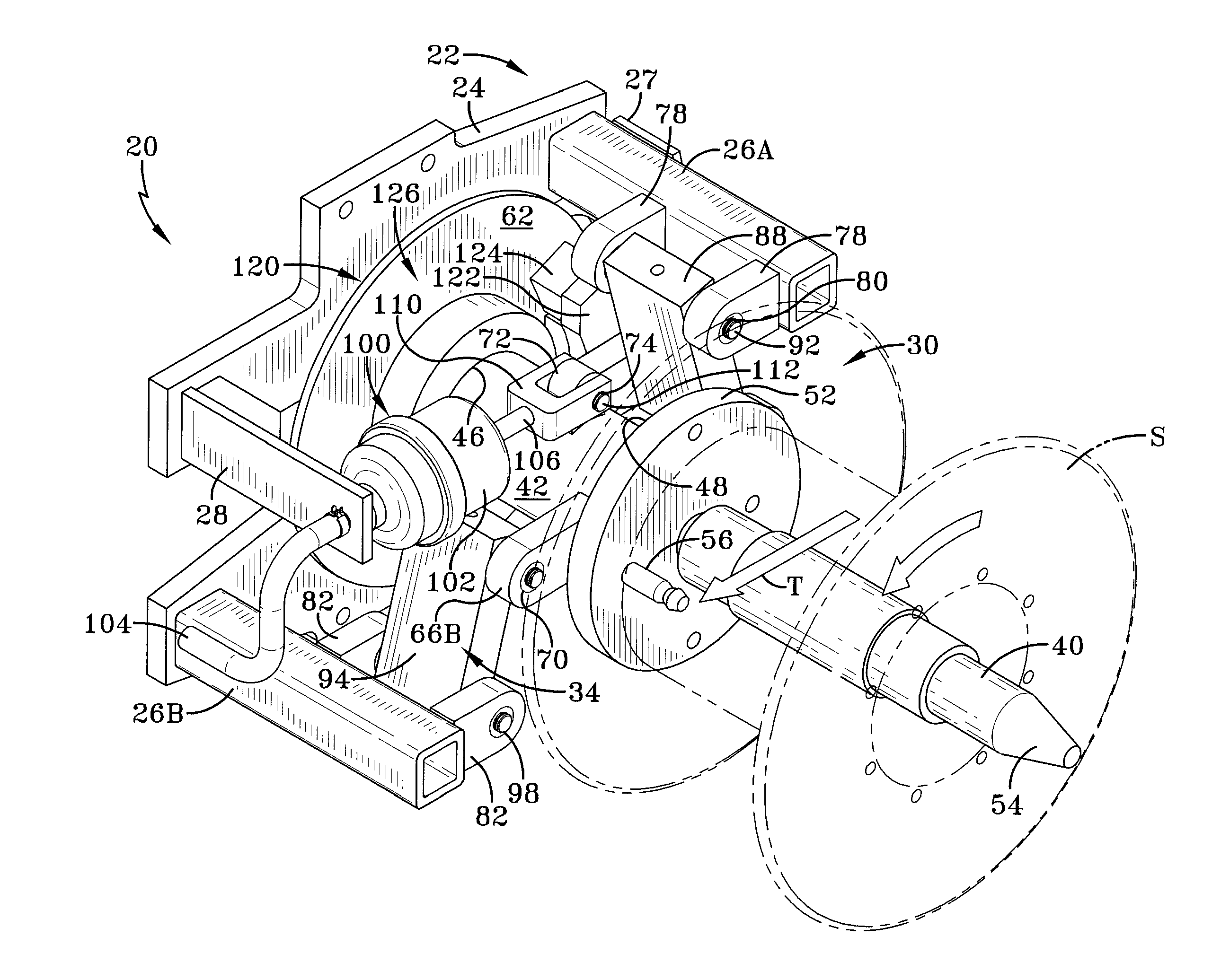
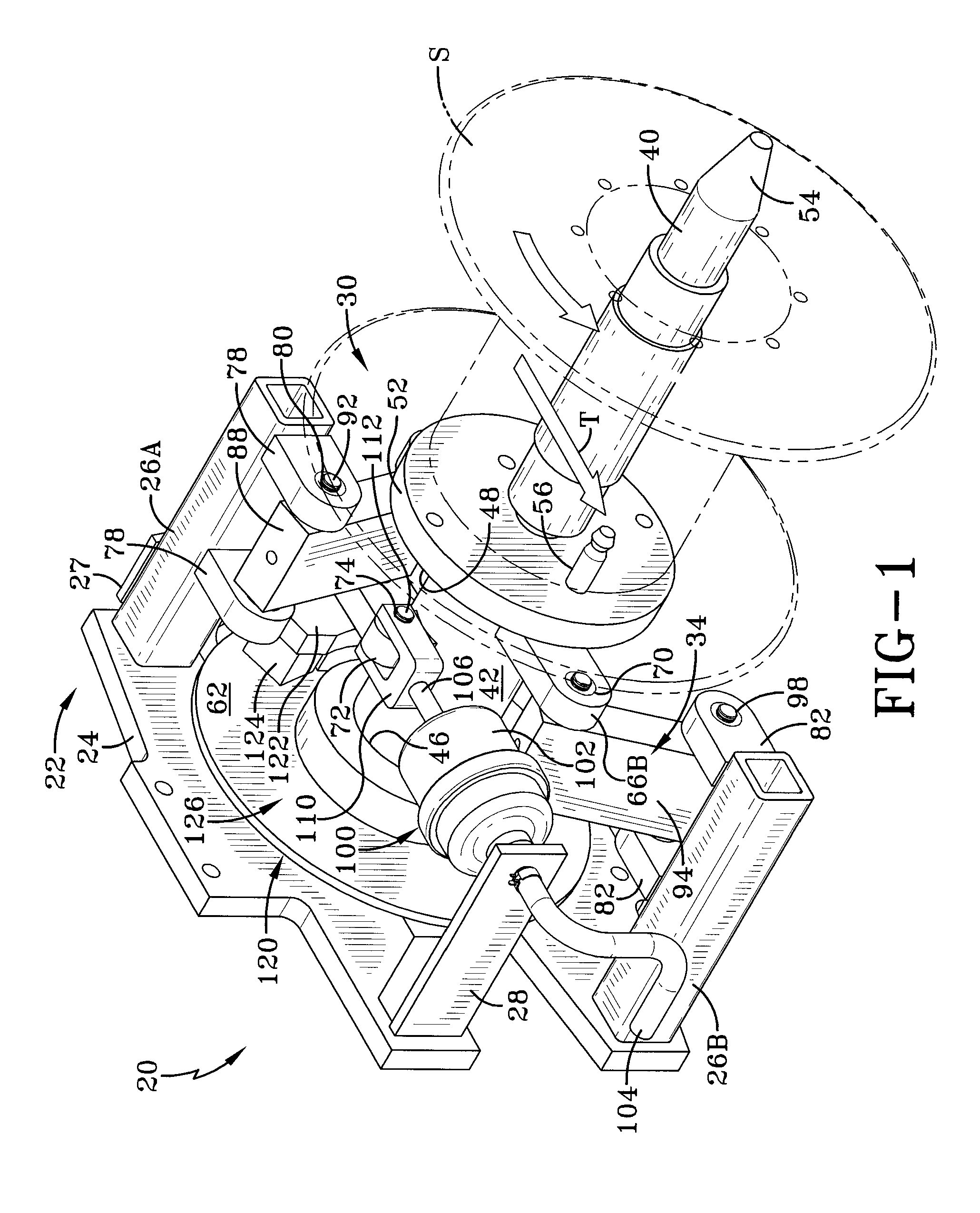
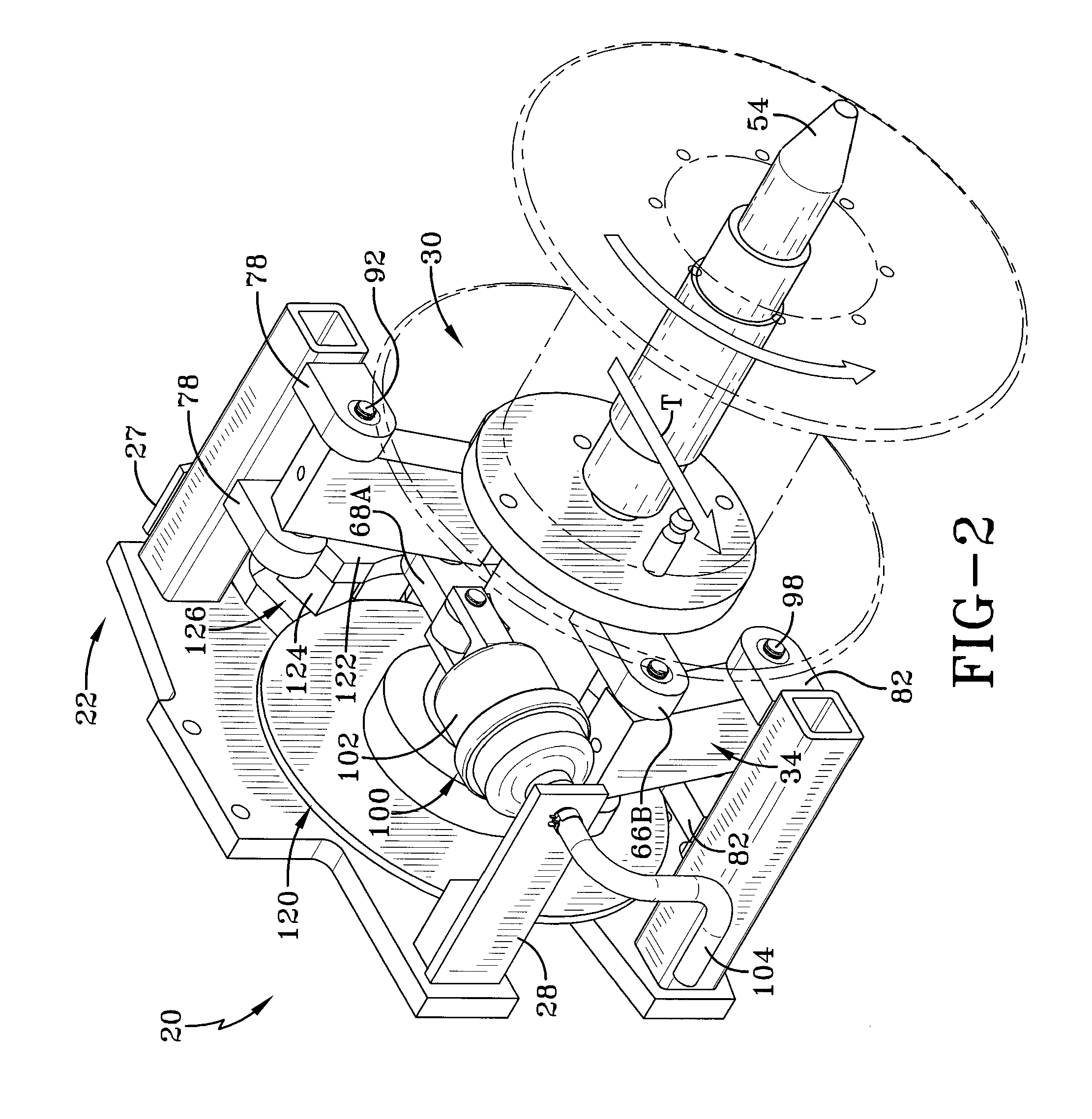
[0025]An exemplary self-compensating filament tension control device with eddy current braking according to the concepts of the present invention is generally indicated by the numeral 20 as seen in FIGS. 1-5. The tension control device 20 includes a fixed support 22 that is affixed to or is part of a creel or other support structure which is part of a machine that processes individual strands of filamentary material into a finished manufactured item. It will be appreciated that the creel likely supports multiple devices 20 as needed. The fixed support 22 includes a support frame 24 which is mounted on the creel via bolts, welding or other secure attachment. The support frame 24 includes at least two support arms 26 extending substantially perpendicularly therefrom and wherein the support arms 26 are utilized to support or carry other components of the control device 20. The support arms 26 are further identified as an upper support arm 26A and a lower support arm 26B.

[0026]The fixed su


PUM


Abstract

A self-compensating tension control device for regulating the payout of filamentary material from a spool includes a fixed support and a spindle assembly rotatably carrying the spool. A tension force applied to the filamentary material, in opposition to a biasing force, moves the spindle assembly linearly in relation to the fixed support. An eddy current braking system includes a conductive member rotatable with the spindle assembly and a magnetic member carried by the fixed support. The spindle assembly and the conductive member move linearly toward a side-by-side relationship with the magnetic member when the tension force applied to the filamentary material is reduced and unable to overcome the biasing force. Linear movement of the spindle assembly and the associated conductive member can be obtained by either a straight line mechanism or a linear ball bushing mechanism. A supplemental brake may also be used.

Description


Claims


Application Information

Patent Timeline
Owner RJS
Why Eureka
Try Eureka