Combustion apparatus and gas turbine engine

a combustion apparatus and gas turbine engine technology, applied in the field of combustion apparatus, can solve the problems of direct adverse effects of nox emissions and higher flame temperatures, and achieve the effects of increasing the life of the combustion apparatus, good supply of oxidant, and effective heat removal through the cavity

Inactive Publication Date: 2014-05-29
SIEMENS AG
View PDF11 Cites 5 Cited by
  • Summary
  • Abstract
  • Description
  • Claims
  • Application Information

AI Technical Summary

Benefits of technology

The present invention relates to a combustion apparatus with two channels separated by a common wall. These channels allow for efficient supplying of oxidants to the devices while also allowing for effective cooling of these components. Additionally, this design allows for equal distribution of oxidants throughout the system without any unevenness or interference. Overall, it provides technical benefits to improving the performance and efficiency of the combustion process.

Problems solved by technology

This patent describes two technical problem addressed by this patent: high flammability temperature (HTP) caused by insufficient air supply during operation at high temperatures. To solve this issue, an improved design has been developed where the combustor's walls are designed with openings for better cooling and reducing noise emission.

Method used


Image

  • Combustion apparatus and gas turbine engine
  • Combustion apparatus and gas turbine engine
  • Combustion apparatus and gas turbine engine

Examples


Embodiment Construction

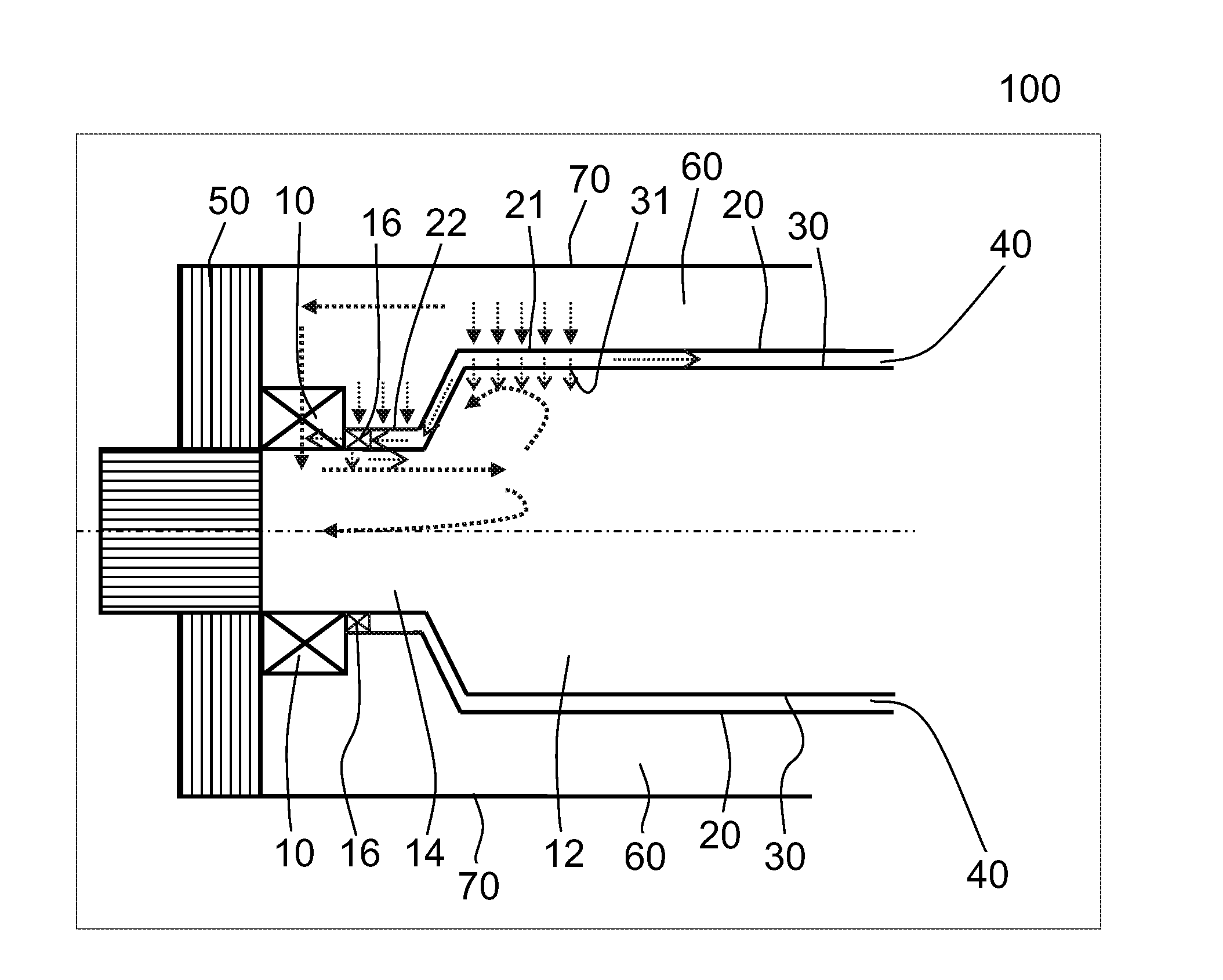
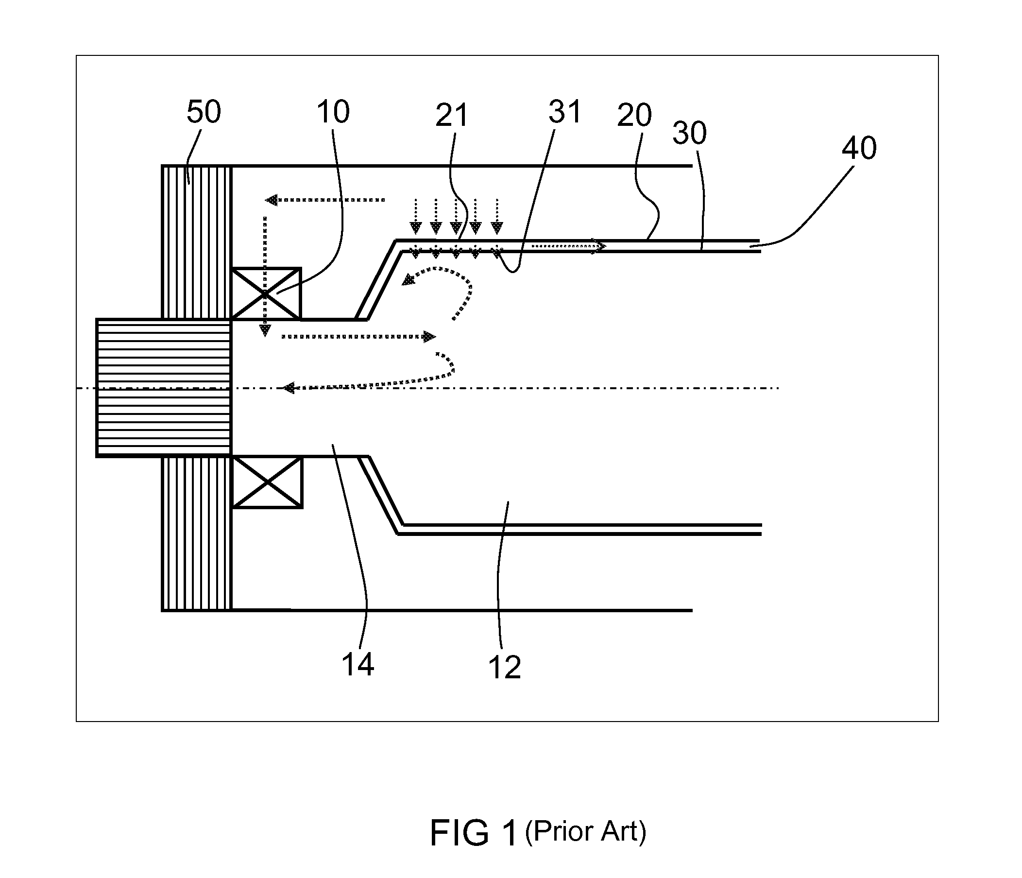
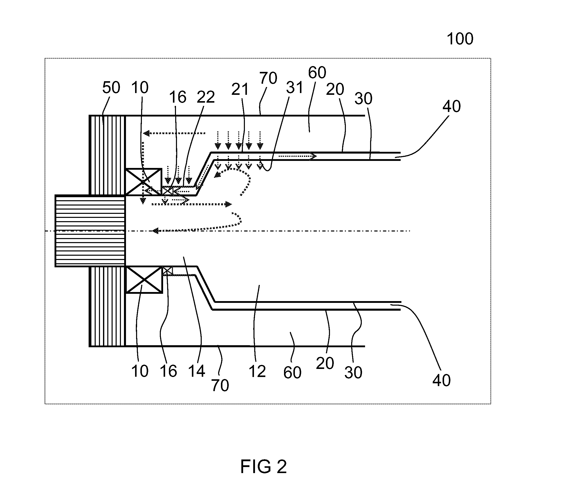
[0038]FIG. 1 of the present invention shows a schematic cross-sectional side view of a combustion apparatus according to the prior art. The combustion apparatus shown in FIG. 1 comprises a combustion chamber 12, a pre-chamber 14 located upstream of the combustion chamber 12, a first device 10 for mixing a fuel with an oxidant, wherein the first device 10 is located upstream of the pre-chamber 14. Moreover, the combustion apparatus according to the prior art also comprises a back plate 50 and an outer casing. The combustion chamber 12 exhibits a first wall 20 and a second wall 30, wherein the first wall 20 is spaced to the second wall 30. Therefore, the first wall 20 and the second wall 30 build a cavity 40. The first wall 20 exhibits a first opening for introducing a coolant into the cavity 40. Furthermore, the second wall 30 exhibits at least one opening 21 for outputting the coolant from the cavity 40 into the combustion chamber 12. Thereby, a cooling of the combustion chamber 12 is


PUM


Abstract

A combustion apparatus includes a combustion chamber, a pre-chamber and a first device for mixing a fuel with an oxidant, the first device being located upstream of the pre-chamber. The combustion chamber and the pre-chamber share a common first and second wall spaced to each other building a cavity. The first wall exhibits at least one first opening in the area of the combustion chamber for introducing a coolant into the cavity. Further, the combustion apparatus has a channel for feeding the oxidant to the first device, whereby the channel is formed by a housing element of the combustion apparatus and the common first wall of the combustion chamber and the pre-chamber. The at least one first opening is located in the area of the combustion chamber. The first wall exhibits at least one second opening, located in the area of the pre-chamber, for introducing the coolant into the cavity.

Description


Claims


Application Information

Patent Timeline
Owner SIEMENS AG
Why Eureka
Try Eureka