Durable ballistics target

a ballistics and target technology, applied in the field of target devices, can solve the problems of limited useful life of target apparatus, limited posturing and external visual characteristics, and unrealistic two-dimensional or three-dimensional appearance of target apparatus, and achieve the effect of increasing the overall lifespan of target apparatus

Inactive Publication Date: 2014-08-28
BRISTOL ENVIRONMENTAL REMEDIATION SERVICES
View PDF6 Cites 5 Cited by
  • Summary
  • Abstract
  • Description
  • Claims
  • Application Information

AI Technical Summary

Benefits of technology

The technical effect of this patented invention is to provide an improved target device for firearms that can resist repetitive impact without losing its strength or performance over time.

Problems solved by technology

This patent describes various technical problem addressed in the previous patents relating to improving the durability of target structures used in ballistics training. Prior art proposals involve using expensive materials like stout foils or laminar sheets, while some proposed solutions include adding a reflective layer to increase visibility and reduce wear. Additionally, current methods require frequent replacements of worn parts due to damage caused by heavy hitting or collateral damage. Therefore, the goal of the present invention is to develop an improved target apparatus that overcomes these limitations and achieves better durability.

Method used


Image

  • Durable ballistics target
  • Durable ballistics target
  • Durable ballistics target

Examples


Embodiment Construction

[0027]In the following discussion that addresses a number of embodiments and applications, reference is made to the accompanying drawings that form a part hereof, and, in which is shown by way of illustration, specific embodiments in which the invention may be practiced. It is to be understood that other embodiments may be utilized and changes may be made without departing from the scope of the present disclosure.

[0028]Various inventive features are described below that can each be used independently of one another or in combination with other features. However, any single inventive feature may not address any of the problems discussed above or only address one of the problems discussed above. Further, one or more of the problems discussed above may not be fully addressed by any of the features described below.

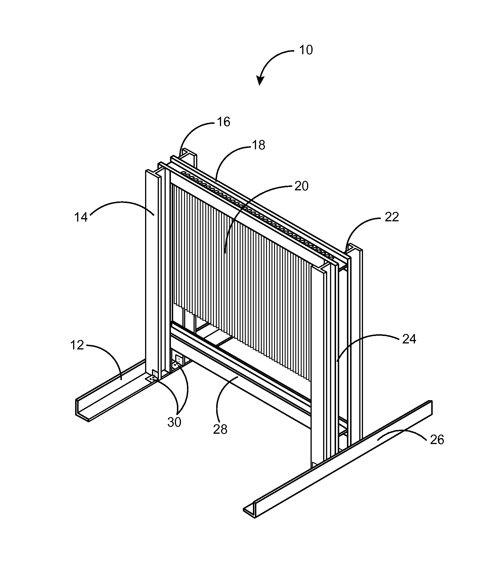
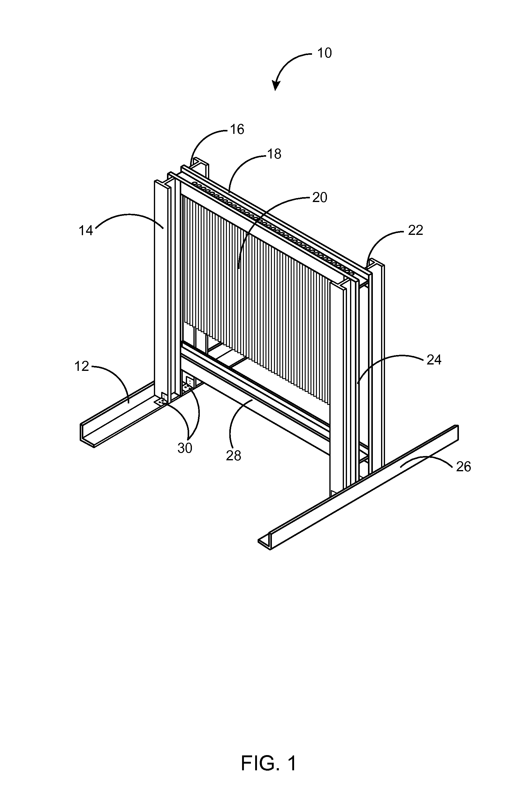
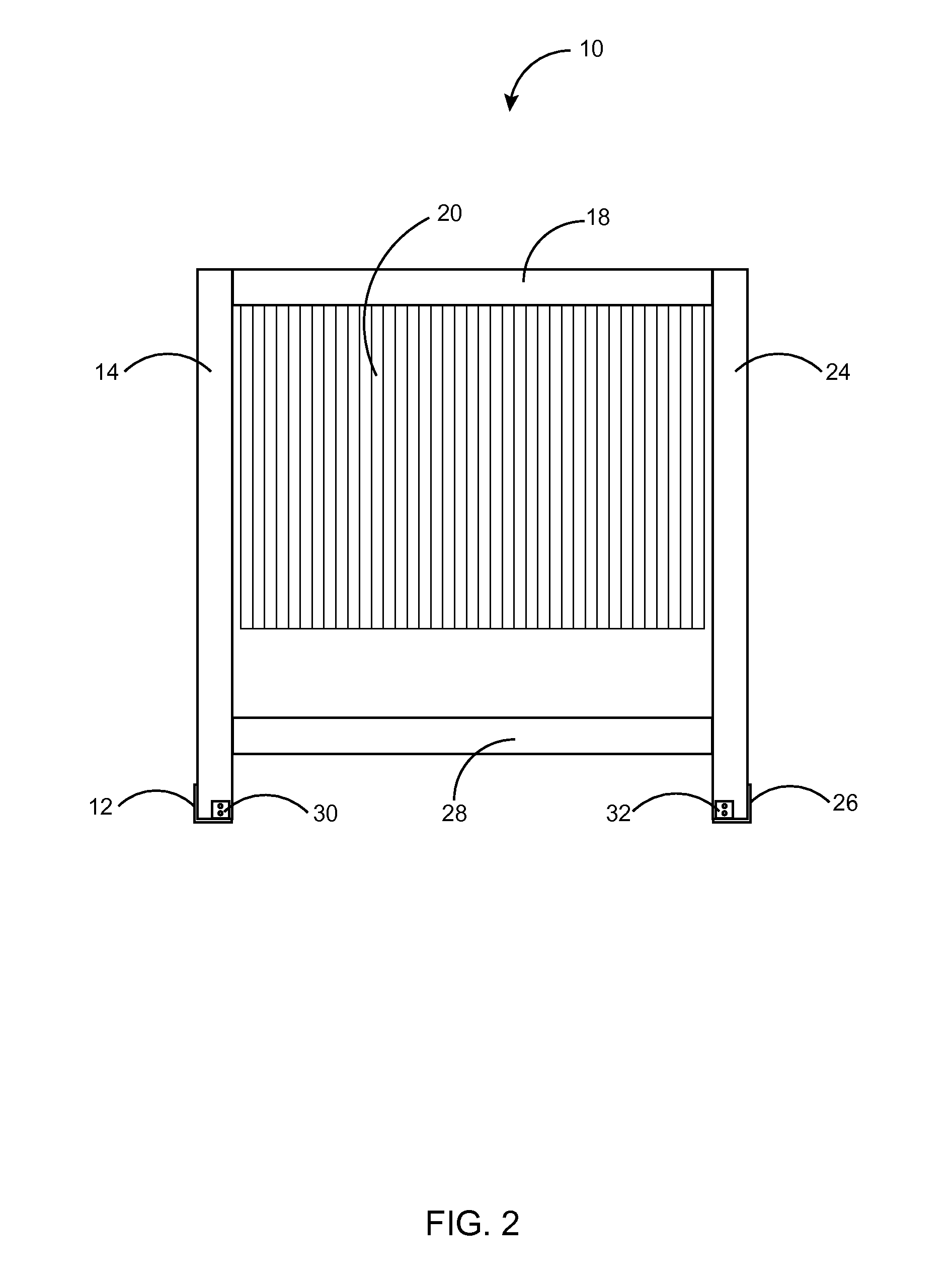
[0029]Referring to FIG. 1 and FIG. 2, FIG. 1 is a perspective view of a first embodiment of a target apparatus 10 and FIG. 2 is a front view of the first embodiment of the target


PUM


Abstract

A target apparatus comprises a plurality of cables and a rigid frame wherein each cable is attached to the rigid frame at least one end of the cable. The plurality of cables is attached to the frame in staggered orientation to one another, and each of the plurality of cables is interchangeable with any other cable of congruent dimension. The plurality of cables is attached to the frame in zigzag orientation to one another. The impact of bullets, mortars, and varying other ammunition rounds upon the plurality of cables is dampened in the loose hanging cables, thereby resulting in a less violent blow to the overall target apparatus. The target apparatus is capable of multiple uses before total destruction of the target apparatus.

Description


Claims


Application Information

Patent Timeline
Owner BRISTOL ENVIRONMENTAL REMEDIATION SERVICES
Why Eureka
Try Eureka