Compact thermal aiming sight

a thermal aiming and sight technology, applied in the field of sight for aiming a weapon, can solve the problems of ineffective use of sight, telescopic and open alignment type sights have the disadvantage of requiring alignment, and the range of sights is limited,

Inactive Publication Date: 2014-09-18
ROCHESTER PRECISION OPTICS LLC
View PDF8 Cites 3 Cited by
  • Summary
  • Abstract
  • Description
  • Claims
  • Application Information

AI Technical Summary

Benefits of technology

This technology solves problems when trying to fire weapons without looking down towards their targets due to poor visibility caused by low lights during night time periods. It uses special optics called cameras attached to guns and displays images taken through them. Users can see what they're doing right now but only within certain limits depending on how far away they have been located.

Problems solved by technology

This patents describes different ways for improving firearms performance when aimed towards their targets during training sessions. These techniques involve adjustable lenses like tungsten bulbs and reflective mirrors which allow users to accurately position themselves relative to these devices without having them look upward looking through windows they may encounter due to darkness or poor visibility caused by low ambient sunlight levels. Additionally, there has been developed other methods involving cameras but this can only provide images within certain ranges depending upon factors like brightness level.

Method used


Image

  • Compact thermal aiming sight
  • Compact thermal aiming sight
  • Compact thermal aiming sight

Examples


Embodiment Construction

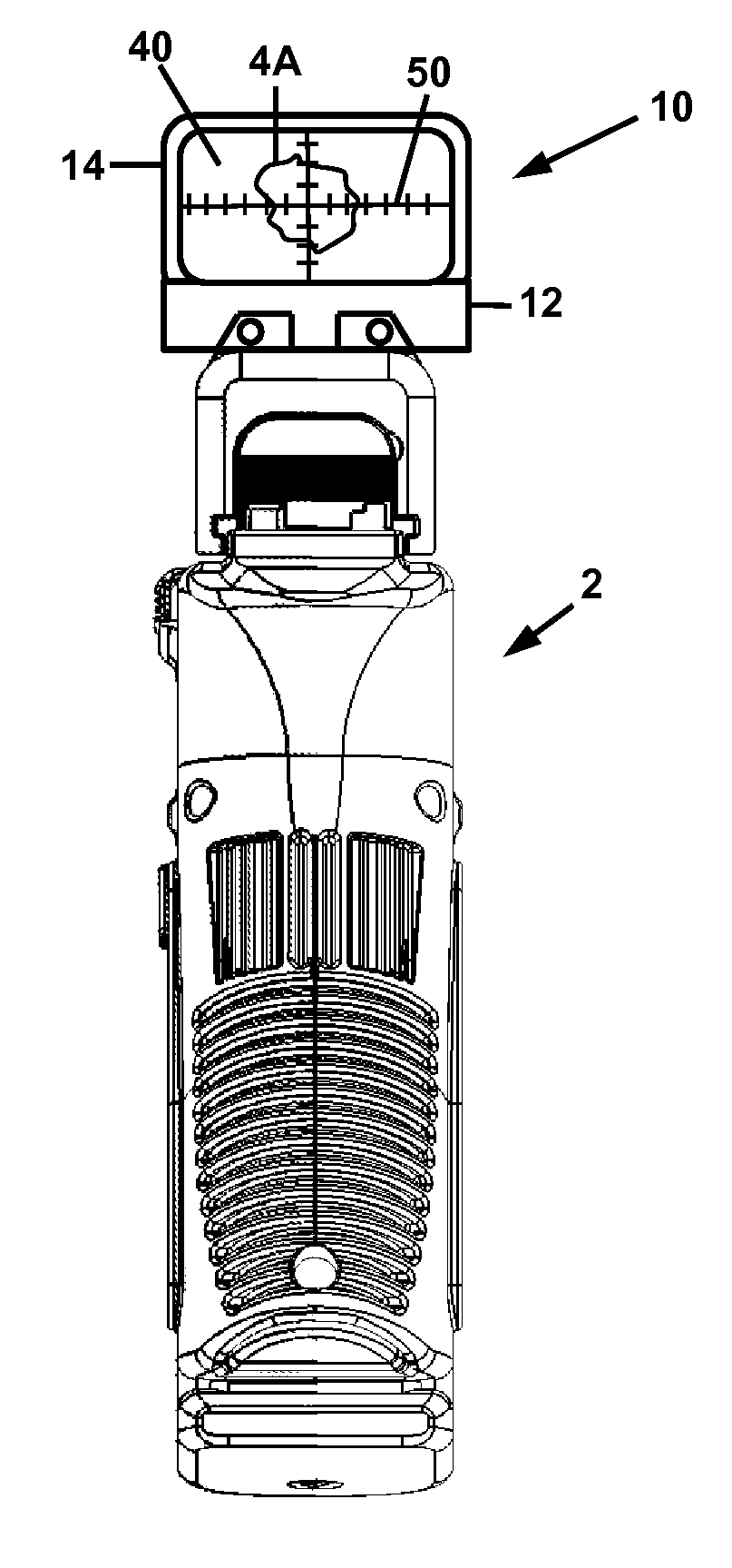
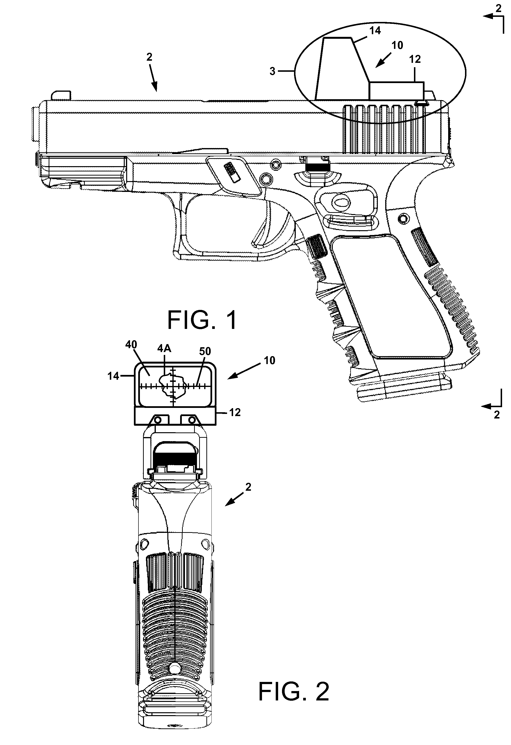
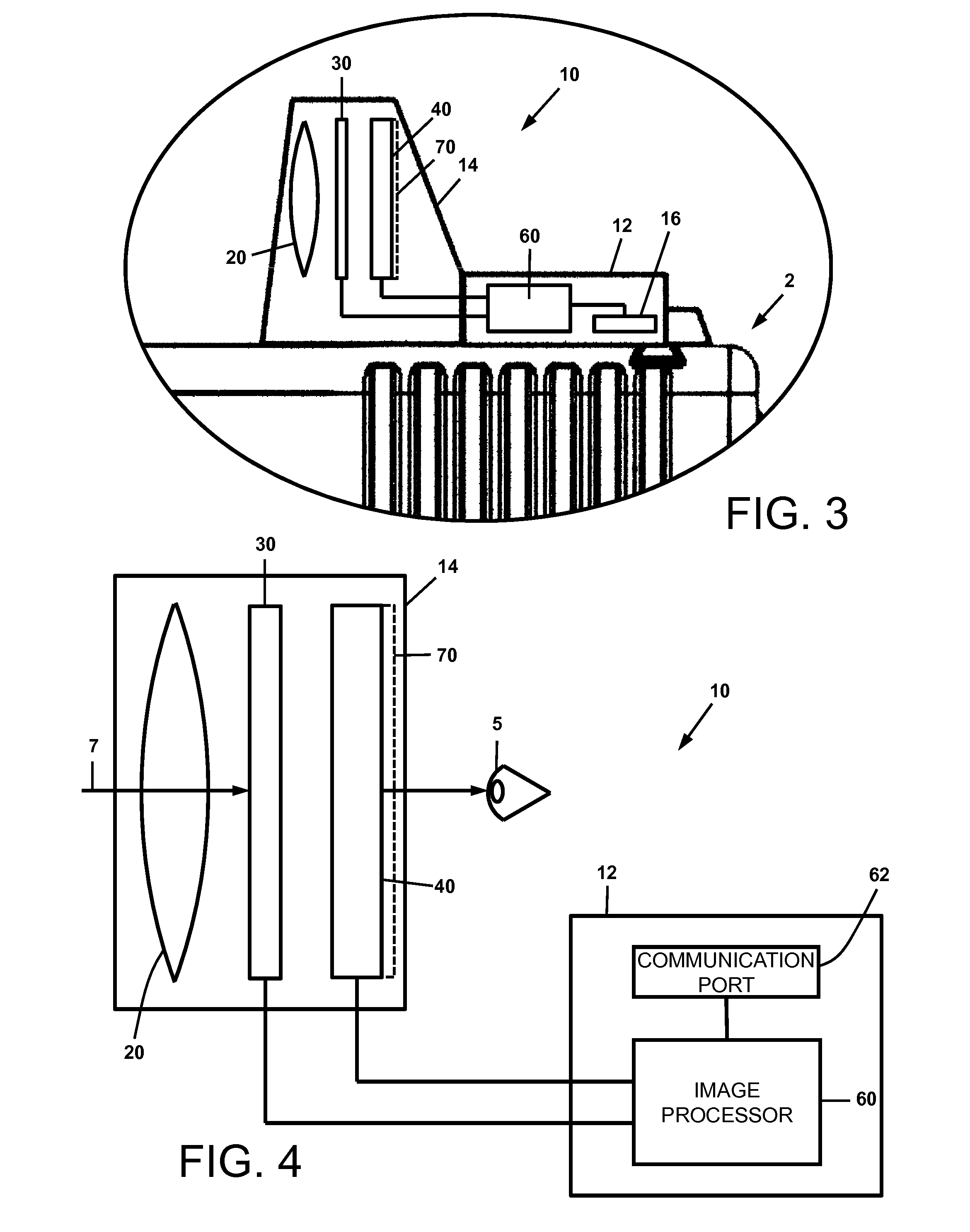
[0020]For a general understanding of the present disclosure, reference is made to the drawings. In the drawings, like reference numerals have been used throughout to designate identical elements. In the following disclosure, the present invention is described in the context of its use as a thermal sight for a weapon. However, it is not to be construed as being limited only to use in weapon aiming applications. The invention is adaptable to any use in which aiming or alignment of an object relative to another object is desirable. Additionally, the description may identify certain components with the adjectives “top,”“upper,”“bottom,”“lower,”“left,”“right,” etc. These adjectives are provided in the context of the orientation of the drawings, which is arbitrary. The description is not to be construed as limiting the instant sight to use in a particular spatial orientation. The instant sight may be used in orientations other than those shown and described herein.

[0021]With reference now to


PUM


Abstract

A sight attachable to a weapon and comprising an objective lens, an image display, and a digital reticle. The objective lens focuses infrared light received from a scene onto a thermal imager, which is comprised of a focal plane array that detects infrared radiation in the scene focused by the lens. The image display is in signal communication with the thermal imager and provides an image of the received infrared light from the scene. The image rendered by the display is visible to the user. The digital reticle is rendered on the display and provides an aim point of the weapon upon a target in the scene. The image of the scene and superimposed reticle are directly viewable by a user with the aim point of the weapon upon the target being maintained constant over a range of viewing angles that depart from a viewing angle perpendicular to the display.

Description


Claims


Application Information

Patent Timeline
Owner ROCHESTER PRECISION OPTICS LLC
Why Eureka
Try Eureka