Method of manufacturing a near-field light generator including a waveguide and a plasmon generator

Active Publication Date: 2014-10-02
HEADWAY TECH INC
View PDF3 Cites 0 Cited by
  • Summary
  • Abstract
  • Description
  • Claims
  • Application Information

AI Technical Summary

Benefits of technology

[0016]It is an object of the present invention to provide a method of manufacturing a near-field light generator and a method of manufacturing a waveguide included in the near-field light

Problems solved by technology

Making the magnetic fine particles smaller, however, causes the problem that the magnetic fine particles drop in the thermal stability of magnetization.
However, increasing the anisotropic energy of the magnetic fine particles leads to an increase in coercivity of the recording medium, and this makes it difficult to perform data writing with existing magnetic heads.
The above-described manufacturing method for the near-field light generator, however, has a problem that hampers accurate control of the thickness of the plasmon generator.
In the above-described manufacturing method for the near-field light g

Method used


Image

  • Method of manufacturing a near-field light generator including a waveguide and a plasmon generator
  • Method of manufacturing a near-field light generator including a waveguide and a plasmon generator
  • Method of manufacturing a near-field light generator including a waveguide and a plasmon generator

Examples


Embodiment Construction

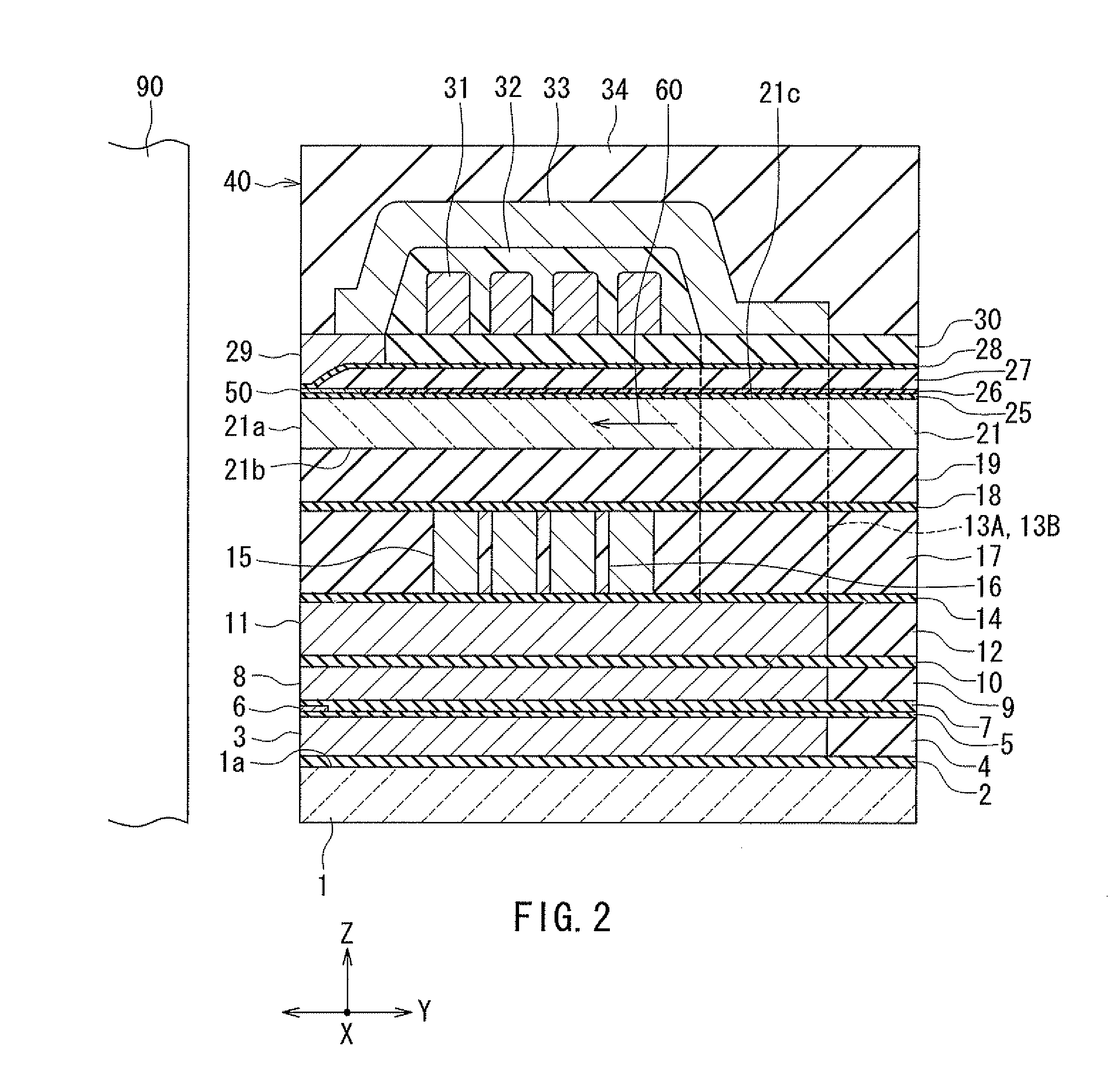
[0042]An embodiment of the present invention will now be described in detail with reference to the drawings. First, reference is made to FIG. 2 and FIG. 3 to describe the configuration of a thermally-assisted magnetic recording head of the embodiment of the invention. FIG. 2 is a cross-sectional view showing the configuration of the thermally-assisted magnetic recording head. FIG. 3 is a front view showing the medium facing surface of the thermally-assisted magnetic recording head.

[0043]The thermally-assisted magnetic recording head of the embodiment is for use in perpendicular magnetic recording, and is in the form of a slider to fly over the surface of a rotating recording medium. When the recording medium rotates, an airflow passing between the recording medium and the slider causes a lift to be exerted on the slider. The slider is configured to fly over the surface of the recording medium by means of the lift.

[0044]As shown in FIG. 2, the thermally-assisted magnetic recording head


PUM


Abstract

In a method of manufacturing a near-field light generator, a structure including a core and a polishing stopper layer disposed on the top surface of the core is formed on a first cladding layer. Next, a cladding material layer is formed to cover the first cladding layer and the structure. The cladding material layer is then polished until the polishing stopper layer is exposed. Next, the polishing stopper layer is removed so that the cladding material layer has a protruding portion protruding upward to a higher level than the top surface of the core. The cladding material layer is then polished so as to remove the protruding portion and thereby make the cladding material layer into a second cladding layer. Then, a third cladding layer and a plasmon generator are formed.

Description


Claims


Application Information

Patent Timeline
Owner HEADWAY TECH INC
Why Eureka
Try Eureka