Shaping die for chip package leads
- Summary
- Abstract
- Description
- Claims
- Application Information
AI Technical Summary
Benefits of technology
Problems solved by technology
Method used
Image

Examples
first embodiment
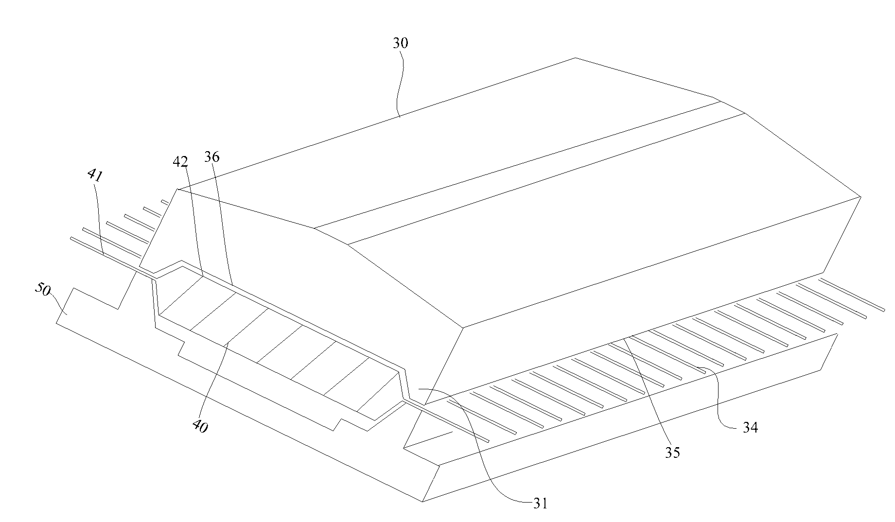
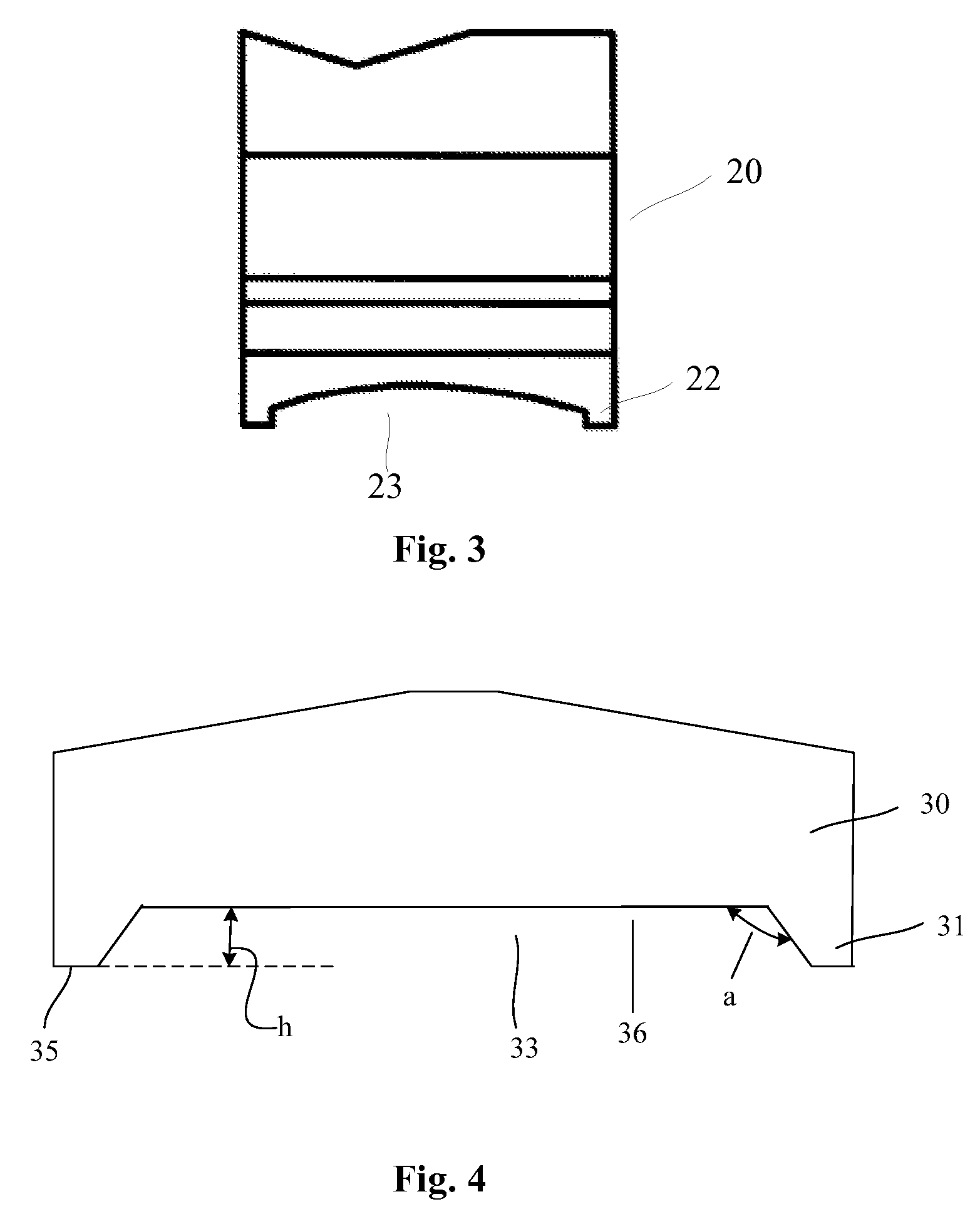
[0038]FIGS. 4 and 5 are the front view and the left view of the shaping die for chip package leads according to the invention respectively.
[0039]The shaping die for chip package leads shown in FIGS. 4 and 5 comprises a base portion 30 and lead pressing portions 31 extending from the opposite sides of the base portion 30. The lead pressing portions 31 and the bottom surface of the base portion 30 define a groove 33 for holding the TSOP package. The lead pressing portions 31 have contact portions 35 contacting with the TSOP package leads.
[0040]The base portion 30 is generally made from alloy materials with higher hardness. The inner surface of the groove 33 is planar. The groove 33 is configured to hold the TSOP package when shaping the TSOP package leads. Thus, the shape of the groove 33 matches with that of the TSOP package and the lateral dimension of the groove 33 is slightly bigger than that of the TSOP package to facilitate the receiving and holding of the TSOP package. The depth h
second embodiment
[0049]FIGS. 8 and 9 are the front view and the left view of the shaping die for chip package leads according to the invention respectively.
[0050]The shaping die for chip package leads shown in FIGS. 8 and 9 comprises a base portion 30 and lead pressing portions 31 extending from the opposite sides of the base portion 30. The lead pressing portions 31 and the bottom surface of the base portion 30 define a groove 33 for holding the TSOP package. The lead pressing portions 31 have contact portions 35 contacting with the TSOP package leads.
[0051]The inner surface of the groove 33 is planar. The groove 33 is configured to hold the TSOP package when shaping the TSOP package leads. Thus, the shape of the groove 33 matches with that of the TSOP package and the lateral dimension of the groove 33 is slightly bigger than that of the TSOP package to facilitate the receiving and holding of the TSOP package. The depth h of the groove 33 corresponds to the maximum distance between the leads and the s
PUM
| Property | Measurement | Unit |
|---|---|---|
| Angle | aaaaa | aaaaa |
| Angle | aaaaa | aaaaa |
| Depth | aaaaa | aaaaa |
Abstract
Description
Claims
Application Information
 - R&D Engineer
- R&D Manager
- IP Professional
- Industry Leading Data Capabilities
- Powerful AI technology
- Patent DNA Extraction
Browse by: Latest US Patents, China's latest patents, Technical Efficacy Thesaurus, Application Domain, Technology Topic.
© 2024 PatSnap. All rights reserved.Legal|Privacy policy|Modern Slavery Act Transparency Statement|Sitemap