Device for providing pipette tips

a technology for pipette tips and ribs, which is applied in the field of devices for providing pipette tips, can solve the problems of no major friction resistance of the ribs, and achieve the effect of convenient inserting of the carrier

Active Publication Date: 2014-10-16
EPPENDORF SE
View PDF9 Cites 24 Cited by
  • Summary
  • Abstract
  • Description
  • Claims
  • Application Information

AI Technical Summary

Benefits of technology

The technical effect of this patented invention is to provide a device for inserting pipettes into carriers without having to bend them over or under their side. This will make it more convenient and efficient for users who want to use these devices.

Problems solved by technology

The technical problem addressed in this patent is how to accurately attach and remove pipet tips without misalignment during replacement of empty pipettors. Existing solutions involve manually inserting the pipette tips into the holder and removing them afterwards, but current methods require precise alignment and may result in incorrect placement if the pipette tips are wrongly placed.

Method used


Image

  • Device for providing pipette tips
  • Device for providing pipette tips
  • Device for providing pipette tips

Examples


Embodiment Construction

[0059]While this invention may be embodied in many different forms, there are described in detail herein a specific preferred embodiment of the invention. This description is an exemplification of the principles of the invention and is not intended to limit the invention to the particular embodiment illustrated.

[0060]In the present application, the references “top” and “bottom” as well as “vertical” and “horizontal” refer to an arrangement of the device in which the plate-shaped carrier is aligned horizontally, the standing surface of the bottom part sits on a horizontal base, and the carrier is inserted from above into the bottom part.

[0061]In the following explanation of different carriers of the device according to the invention, components with the same designation are provided with the same reference numbers.

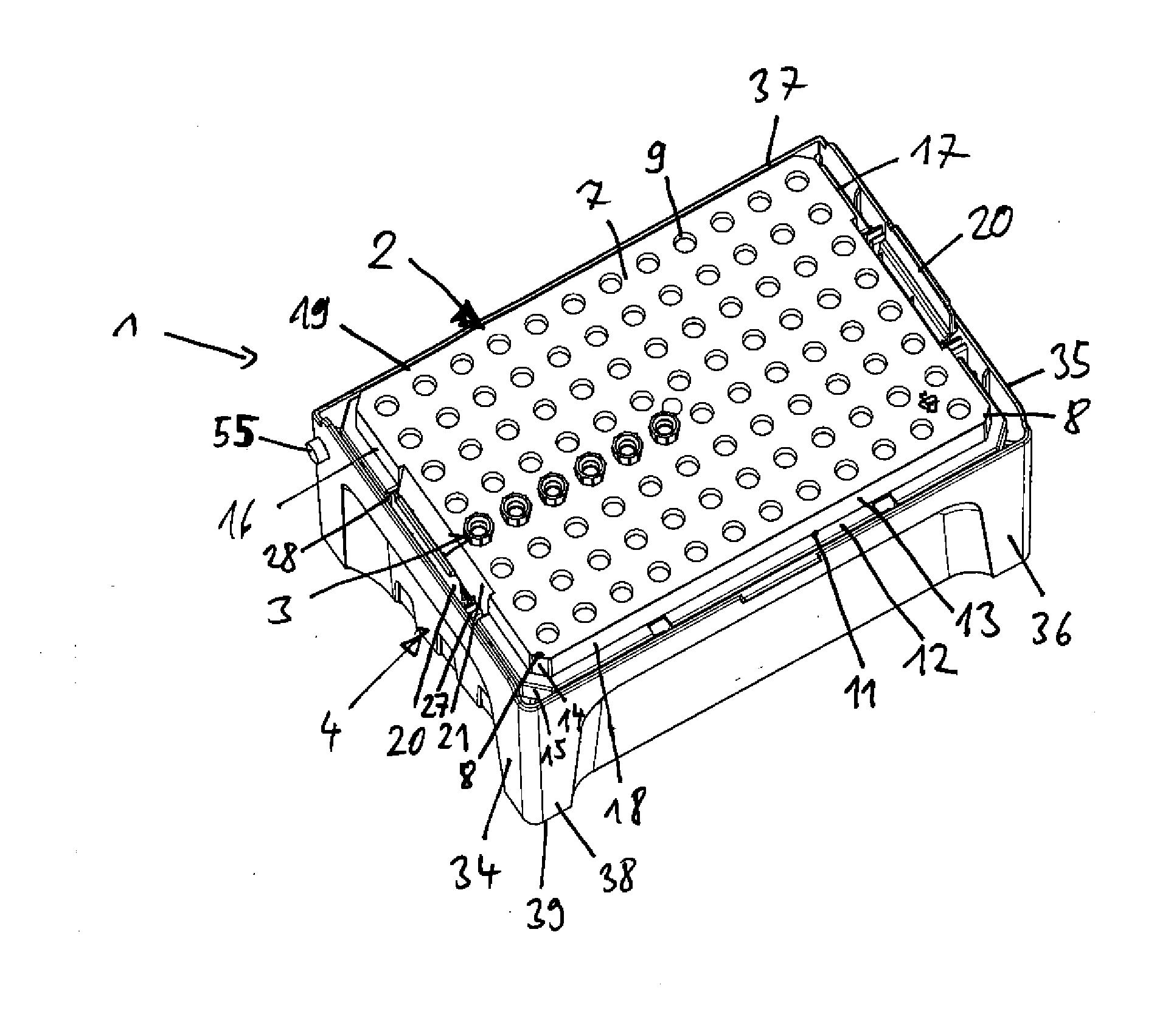
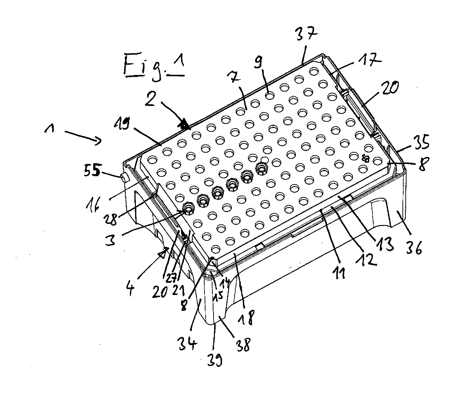
[0062]According to FIG. 1, the device 1 according to the invention for providing pipette tips comprises a substantially plate-shaped and substantially rectangular carrier 2 th


PUM


Abstract

A device for providing pipette tips includes a plate-shaped carrier with a base surface, holes in the carrier perpendicular to the base surface, at least one vertically running cut-out in the outer sides of two opposing narrow sides of the carrier to accommodate two vertical guide ribs at a distance from each other, pipette tips in the holes, a bottom part with sidewalls that extend upwards from a standing surface, said sidewalls surrounding a rectangular seat for the carrier with the inserted pipette tips, wherein two opposing first sidewalls project further upward from the standing surface than to opposing second sidewalls, a supporting mechanism on the inner sides of at least two opposing sidewalls to support the carrier in a horizontal alignment at the bottom edges of narrow sides, and two vertical guide ribs engaging in the at least one cut-out when the carrier is placed on the supporting mechanism.

Description


Claims


Application Information

Patent Timeline
Owner EPPENDORF SE
Why Eureka
Try Eureka