Combustion chamber cooling
a combustion chamber and combustion chamber technology, applied in the combustion process, hot gas positive displacement engine plants, lighting and heating apparatus, etc., can solve the problems of insufficient thermal barrier coating on the inside of the liner, and achieve the effect of reducing the number of resonators, reducing costs, and saving air
- Summary
- Abstract
- Description
- Claims
- Application Information
AI Technical Summary
Benefits of technology
Problems solved by technology
Method used
Image

Examples
Embodiment Construction
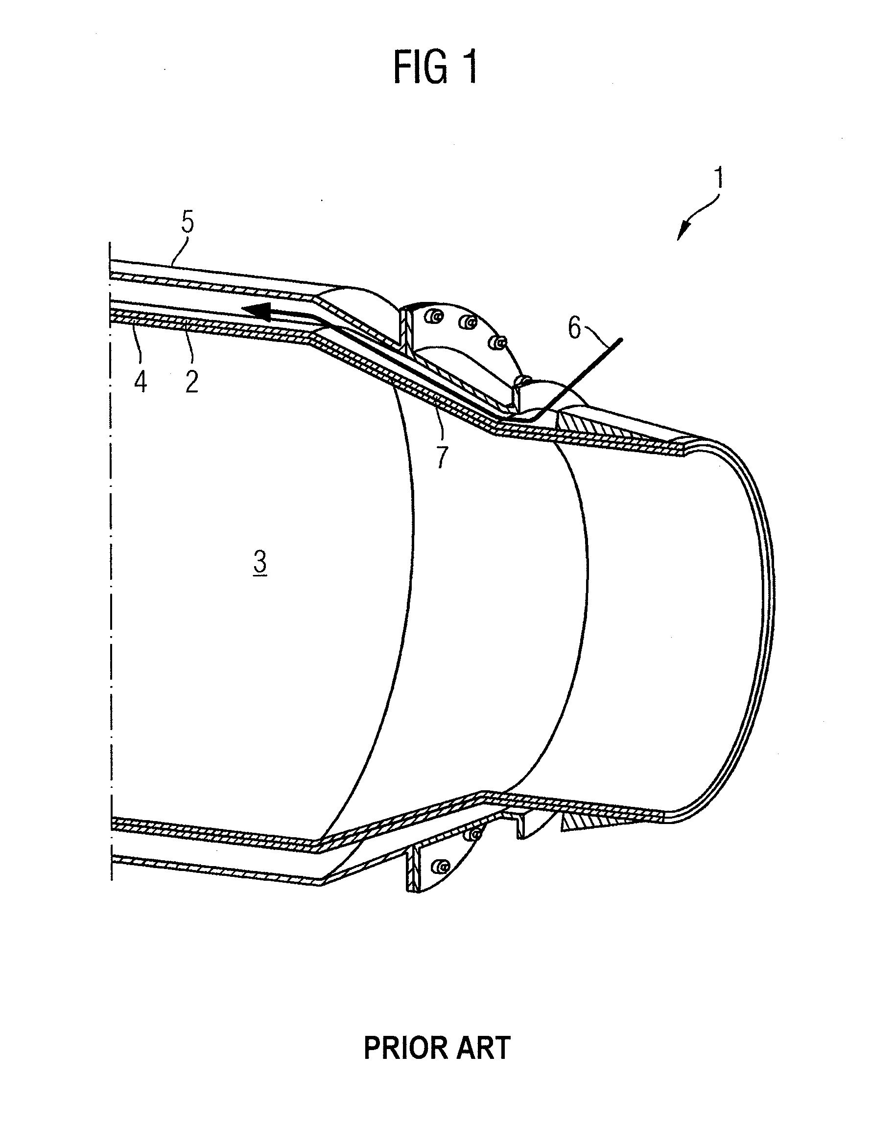
[0032]FIG. 1 shows, schematically and by way of example, a gas turbine combustion chamber 1 according to the prior art with an inner wall 2 (burner liner) which encloses the combustion space 3 and has, on the combustion space side, a thermal protection coating 4, and a sheath 5 surrounding the inner wall 2. Between the inner wall and the sheath 5, cooling air 6 is guided for convectively cooling the inner wall 2. In the transition from the combustion space 3 downstream to the turbine space (not shown), the gas turbine combustion chamber 1 and therefore also the inner wall 2 or the burner liner 2 are conical. This region is therefore also termed the liner cone 7.
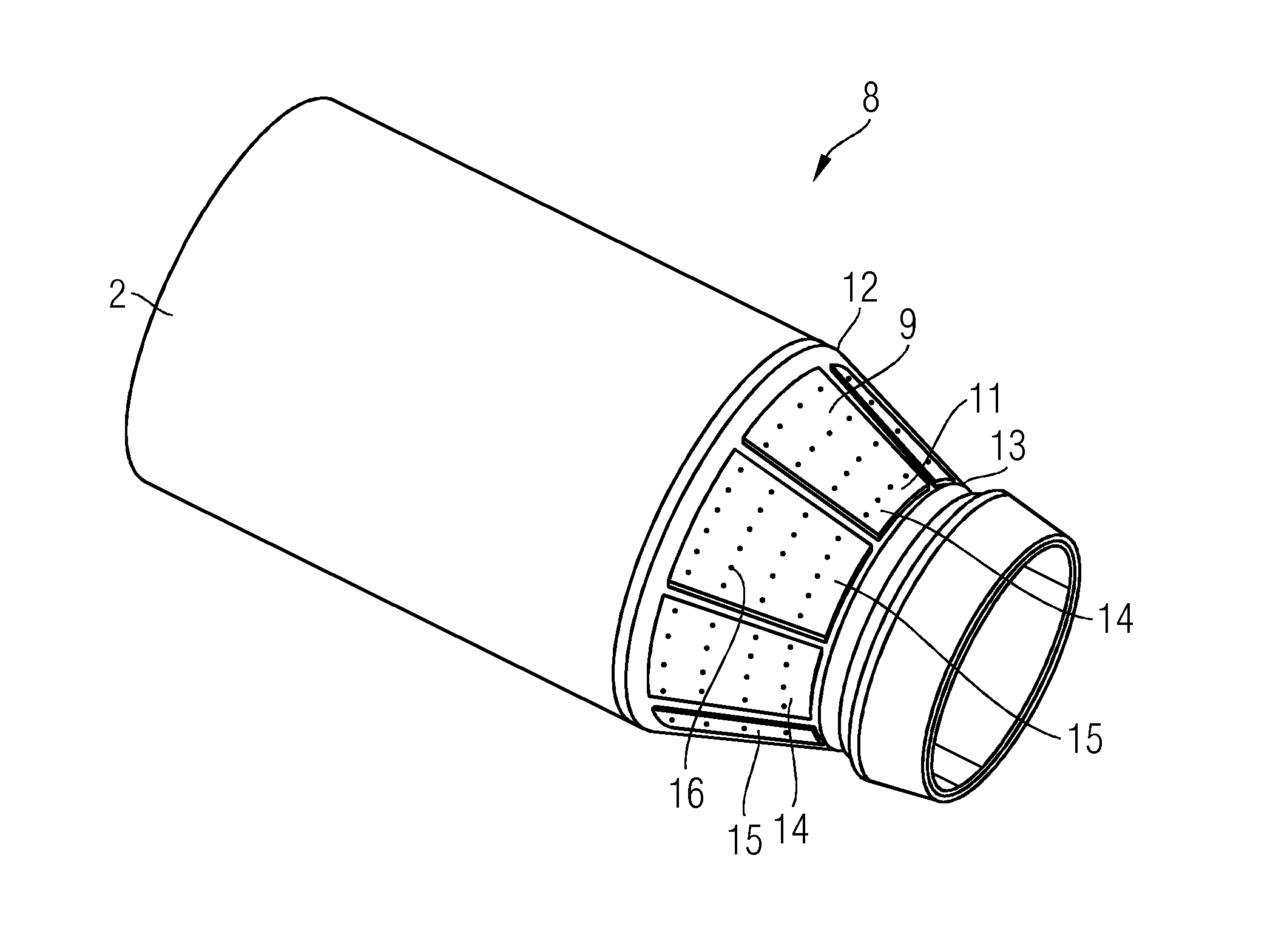
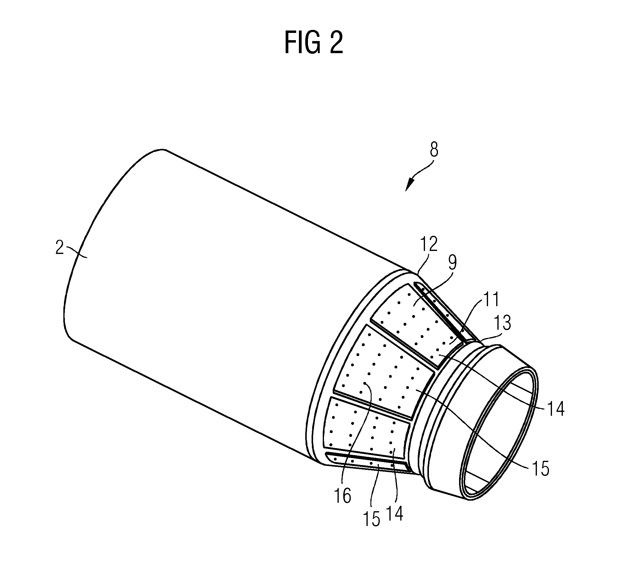
[0033]FIG. 2 shows a gas turbine combustion chamber 8 according to the invention with an inner wall 2 and an outer wall 9 spaced apart therefrom, which form a cavity 10 (see FIGS. 5 and 6). The outer wall 9 is formed by a plate construction, comprised of eight wall elements 11, which are configured and arranged and supported to
PUM
 Abstract
Description
Claims
Application Information
 - R&D Engineer
- R&D Manager
- IP Professional
- Industry Leading Data Capabilities
- Powerful AI technology
- Patent DNA Extraction
Browse by: Latest US Patents, China's latest patents, Technical Efficacy Thesaurus, Application Domain, Technology Topic.
© 2024 PatSnap. All rights reserved.Legal|Privacy policy|Modern Slavery Act Transparency Statement|Sitemap