System and method to defragment a memory
a memory and system technology, applied in the field of defragmenting a memory, can solve the problems of memory fragmentation, difficult to apply certain power saving features in a computing device, memory fragmentation may render pasr ineffective,
- Summary
- Abstract
- Description
- Claims
- Application Information
AI Technical Summary
Benefits of technology
Problems solved by technology
Method used
Image


Examples
first embodiment
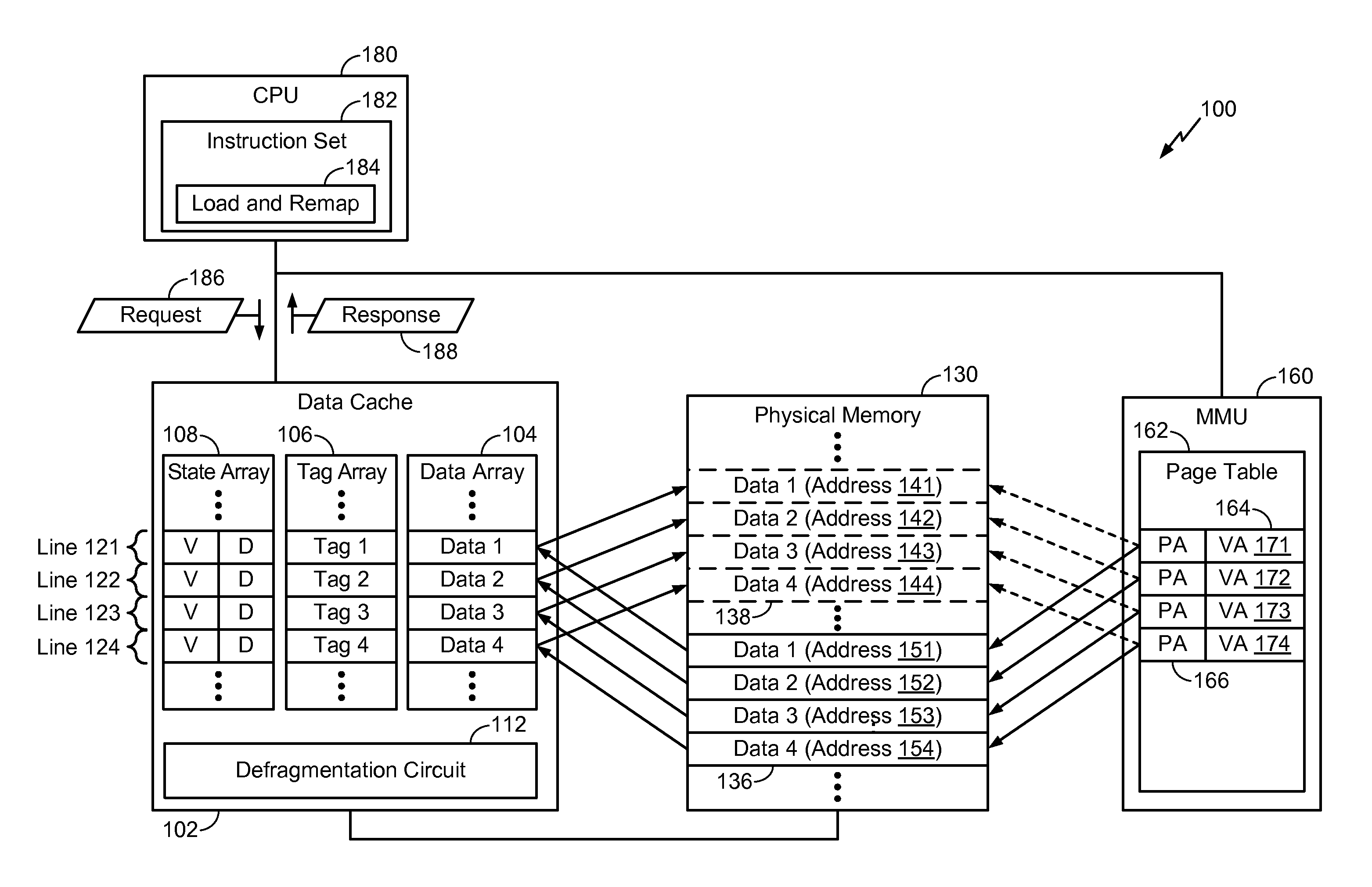
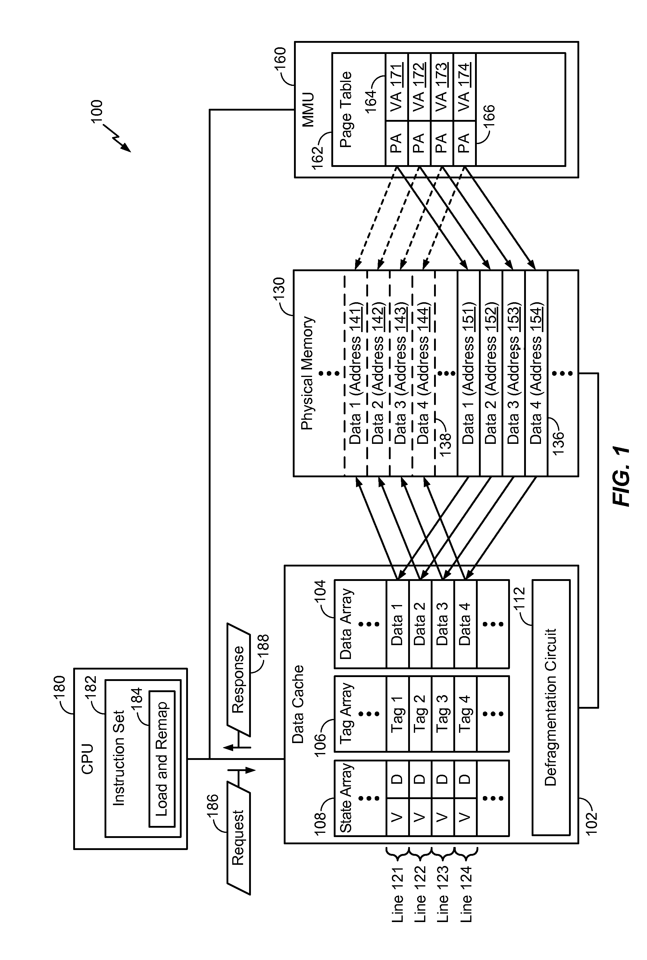
[0053]Referring to FIG. 4, cache-based defragmentation operations performed by a defragmentation circuit (e.g., the defragmentation circuit 312 of FIG. 3A) is depicted and generally designated 400. FIG. 4 illustrates a data cache (e.g., corresponding to the data cache 102 of FIG. 1 and / or the third level data cache 308 of FIG. 3A) including a tag array 402 (e.g., a tag array of an 8-way set associative cache), and a data array 410 (e.g., a data array of the 8-way set associative cache). FIG. 4 also illustrates a main memory 420 (e.g., corresponding to the physical memory 130 of FIG. 1 and / or the physical memory 310 of FIG. 3A) associated with a plurality of addresses. For example, the main memory 420 may be configured to store data at a source address 424 (e.g., corresponding to the source address 352 of FIG. 3B) and a destination address 422 (e.g., corresponding to the destination address 354 of FIG. 3B).
[0054]The tag array 402 may correspond to the tag array 106 of FIG. 1 and the
second embodiment
[0057]Referring to FIG. 5, cache-based defragmentation operations performed by a defragmentation circuit is depicted and generally designated 500. FIG. 5 corresponds to operations when the page segments are the same (A2=B2) but a cache miss occurs. Thus, when the cache-based defragmentation operations are initiated, data corresponding to the source address 424 has not yet been loaded into the cache location 412 of the data array 410 (as shown by a hollow block at the cache location 412). When a request to perform defragmentation operations is received, a cache miss may result.
[0058]The defragmentation circuit (as described with reference to FIG. 4) may load the data stored at the source address 424 into the cache location 412. However, instead of inserting the tag A1 associated with the source address 424 in the tag array 402, the defragmentation circuit may instead insert the tag B1 associated with the destination address 422 in the tag 404. The defragmentation circuit may also mark t
third embodiment
[0059]Referring to FIG. 6, cache-based defragmentation operations performed by a defragmentation circuit is depicted and generally designated 600. FIG. 6 corresponds to operations when the page segments are different (A2 does not equal B2) and a cache hit occurs. The source address 424 may correspond to a first page segment 418 and the destination address 422 may correspond to a second page segment 618. Data corresponding to the source address 424 has been loaded into the cache location 412 of the data array 410 (as shown by a solid block at the cache location 412). When a request to perform defragmentation operations is received, a cache hit results.
[0060]The defragmentation circuit (as described with reference to FIGS. 4 and 5) may move the data stored at the cache location 412 to a second cache location 616 associated with the second page segment 618. The defragmentation circuit may also insert, into the tag array 402, the tag B1 corresponding to the destination address 422 as the t
PUM
 Abstract
Description
Claims
Application Information
 - R&D Engineer
- R&D Manager
- IP Professional
- Industry Leading Data Capabilities
- Powerful AI technology
- Patent DNA Extraction
Browse by: Latest US Patents, China's latest patents, Technical Efficacy Thesaurus, Application Domain, Technology Topic.
© 2024 PatSnap. All rights reserved.Legal|Privacy policy|Modern Slavery Act Transparency Statement|Sitemap