Pressure sensor

Inactive Publication Date: 2015-10-22
FUJIKOKI CORP
View PDF9 Cites 3 Cited by
  • Summary
  • Abstract
  • Description
  • Claims
  • Application Information

AI Technical Summary

Benefits of technology

[0010]Employing the configuration of the invention, it is possible to provide a pressure sensor which is simply configured without a

Problems solved by technology

In addition, the structure of the neu

Method used


Image

  • Pressure sensor
  • Pressure sensor
  • Pressure sensor

Examples


Example

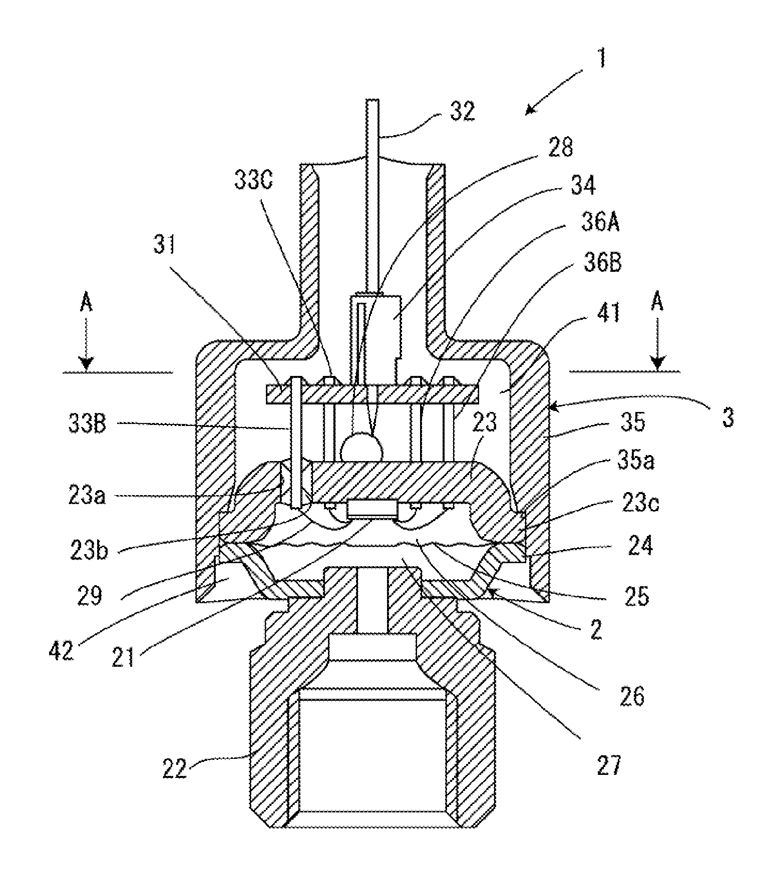
[0014]As illustrated in FIG. 1, a pressure sensor 1 includes a stepped cylinder cover 35. In an opening of the cover 35 having a large diameter, there is mounted a semiconductor pressure detection device 2. The semiconductor pressure detection device 2 includes a base 23 which is provided with a pressure detection element 21 to be described below, a receiving member 24 which supports a fluid inflow section 22 connected to a fluid inflow pipe (not illustrated), and a diaphragm 25 of which the outer peripheral portion is interposed between the base 23 and the receiving member 24.

[0015]An insulative liquid medium such as oil fills a pressure receiving space 26 which is partitioned by the plate-like base 23 and the diaphragm 25. A ball 28 is used to seal a through hole (not illustrated) formed in the base 23 after the pressure receiving space 26 is filled with the liquid medium through the hole, and is fixed to the base 23 by welding.

[0016]The pressure detection element 21 (a pressure sens


PUM


Abstract

According to the invention, a pressure receiving space of a pressure sensor is prevented from being charged. In the pressure sensor, a diaphragm is mounted on a base fixed in a cover to form the pressure receiving space in which oil is sealed. A semiconductor pressure detection device is provided in the pressure receiving space, and adjustment lead pins and an earth-terminal lead pin are connected to terminals of the semiconductor pressure detection device by bonding wires. A wiring substrate is provided with the base of the pressure receiving space interposed and faces the base, and a metal foil is provided such that one or more lead pins of the adjustment lead pins and the earth-terminal lead pin are electrically connected in the wiring substrate. Therefore, the charging of the insulative medium sealed in the pressure receiving space is prevented.

Description


Claims


Application Information

Patent Timeline
Owner FUJIKOKI CORP
Why Eureka
Try Eureka