Information processing apparatus, information processing method, and computer program
a technology of information processing and information processing method, which is applied in the direction of electric/magnetic computing, analogue processes for specific applications, instruments, etc., can solve the problem that no system has been provided that controls the electric power state of the vehicle in a multi-stage manner
- Summary
- Abstract
- Description
- Claims
- Application Information
AI Technical Summary
Benefits of technology
Problems solved by technology
Method used
Image

Examples
first embodiment
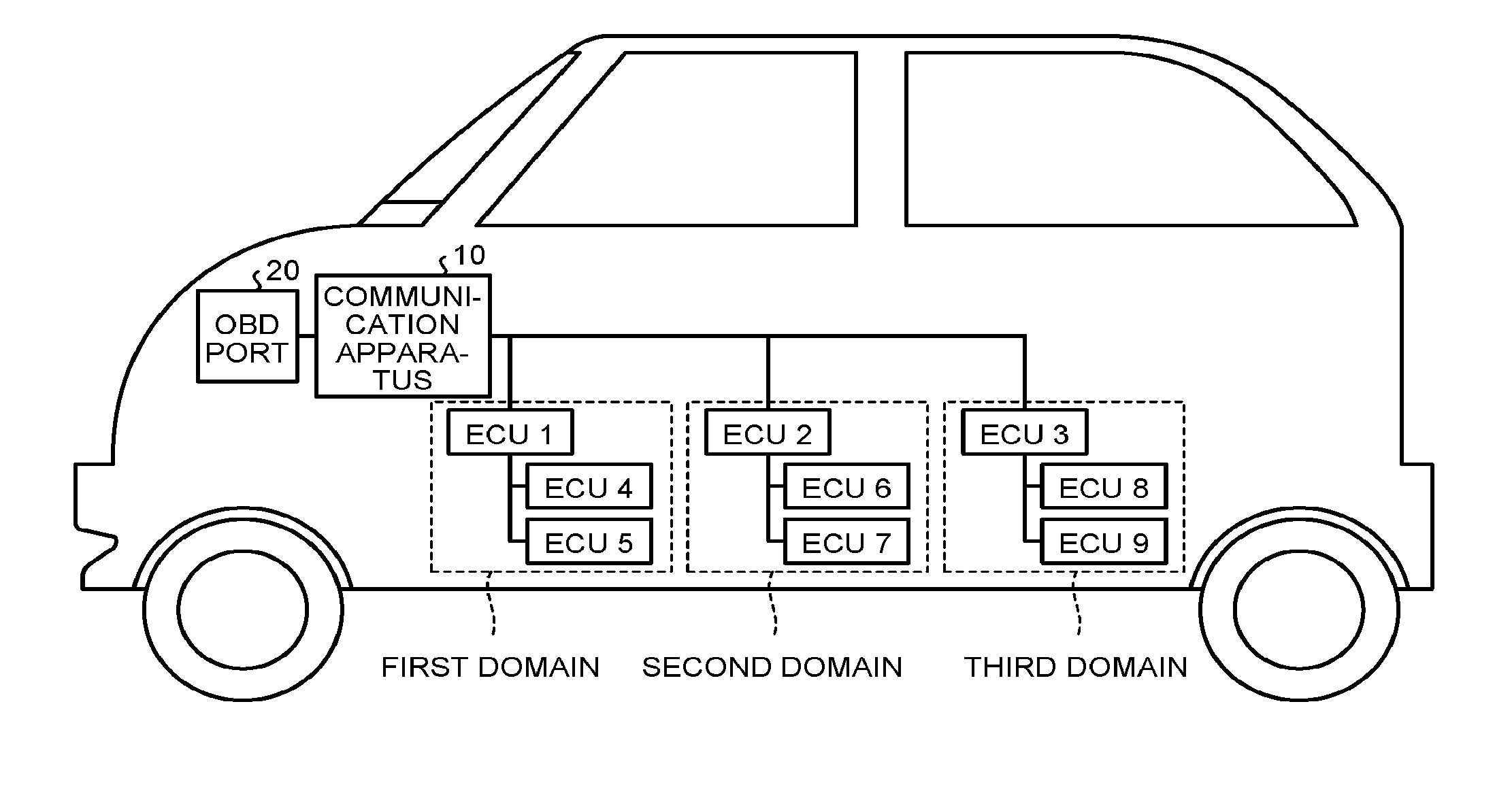
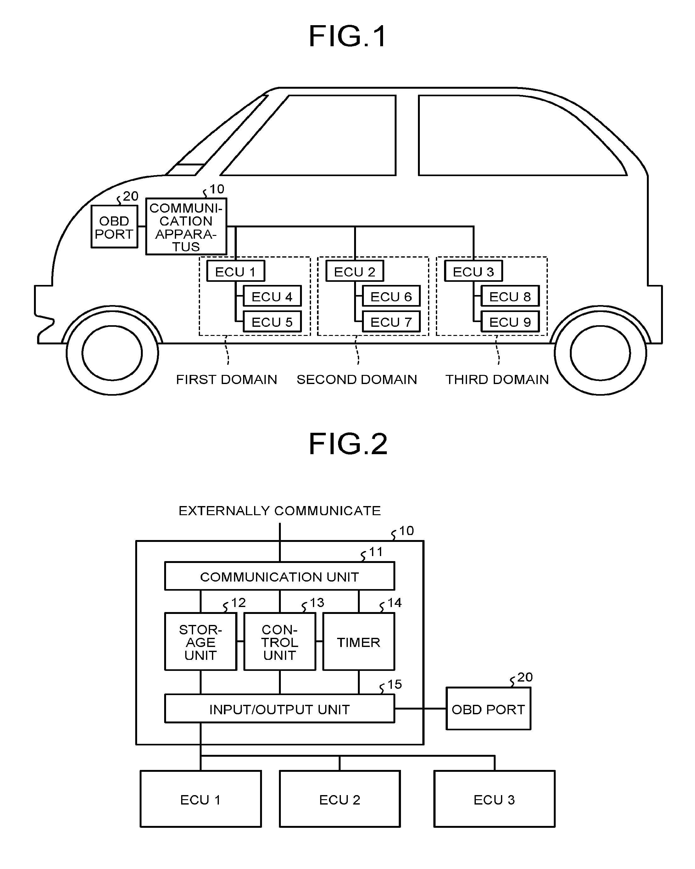
[0027]FIG. 1 is a diagram illustrating an example of the configuration of an electronic control unit (ECU) in a vehicle according to a first embodiment of the present invention. The example illustrated in FIG. 1 includes a plurality of (three in the example illustrated in FIG. 1) domains (control systems), each including a plurality of ECUs (1, 2, and 3). Each of the domains integrally controls a plurality of ECUs belonging to the corresponding domain and is coupled to a communication apparatus 10 externally communicating with a device and the like. The example illustrated in FIG. 1 includes three domains, out of which a first domain includes an ECU 1, an ECU 4, and an ECU 5. The ECU 1 integrally controls the ECU 4 and the ECU 5 and is coupled to the communication apparatus 10. A second domain includes an ECU 2, an ECU 6, and an ECU 7. The ECU 2 integrally controls the ECU 6 and the ECU 7 and is coupled to the communication apparatus 10. A third domain includes an ECU 3, an ECU 8, and
second embodiment
[0056]A second embodiment will now be described. Overlapped explanation with the description in the first embodiment will be omitted as appropriate. The configuration of the ECUs in the vehicle in the present embodiment is the same as that in the first embodiment. However, in the present embodiment, the electric power control unit 104 further includes a function of controlling the electric power state of the own vehicle during running in accordance with the distance that the own vehicle will travel before the own vehicle stops at the traffic light 30. In the present embodiment, if the own vehicle is determined to stop at the nearest traffic light 30, the calculation unit 103 calculates the distance from the present position of the own vehicle to the stop line of the nearest traffic light 30 as the distance that the own vehicle will travel before the own vehicle stops at the traffic light 30. In this example, the calculation unit 103 instructs the ECU controlling the car navigation to c
third embodiment
[0064]A third embodiment will now be described. Overlapped explanation with the description in the first embodiment will be omitted as appropriate. The configuration of the ECUs in the own vehicle in the present embodiment is the same as that in the first embodiment. However, in the present embodiment, as illustrated in FIG. 12, the first acquiring unit 102 acquires only the traffic light information (the packets) transmitted from the traffic light 30 whose distance to the own vehicle is equal to or smaller than a reference value (a radius r in the example illustrated in FIG. 12). If the distance between the own vehicle and the traffic light 30 from which the received packets are transmitted exceeds the radius r, the first acquiring unit 102 discards the received packets.
[0065]The value of the above-described radius r may be unique to the vehicle or determined based on the congestion on the road or the legal speed. If the value of the radius r is unique to the vehicle, it can be set by
PUM
 Abstract
Description
Claims
Application Information
 - R&D Engineer
- R&D Manager
- IP Professional
- Industry Leading Data Capabilities
- Powerful AI technology
- Patent DNA Extraction
Browse by: Latest US Patents, China's latest patents, Technical Efficacy Thesaurus, Application Domain, Technology Topic.
© 2024 PatSnap. All rights reserved.Legal|Privacy policy|Modern Slavery Act Transparency Statement|Sitemap