Electromagnetic switch for starter
a technology of electromagnetic switch and starter, which is applied in the direction of engine starter, machine/engine, relay, etc., can solve the problems of insufficient cleaning of the surface of the contact, reducing etc., and achieves the effect of increasing the life of the contact and suppressing the wear of the conta
- Summary
- Abstract
- Description
- Claims
- Application Information
AI Technical Summary
Benefits of technology
Problems solved by technology
Method used
Image
Examples
second example
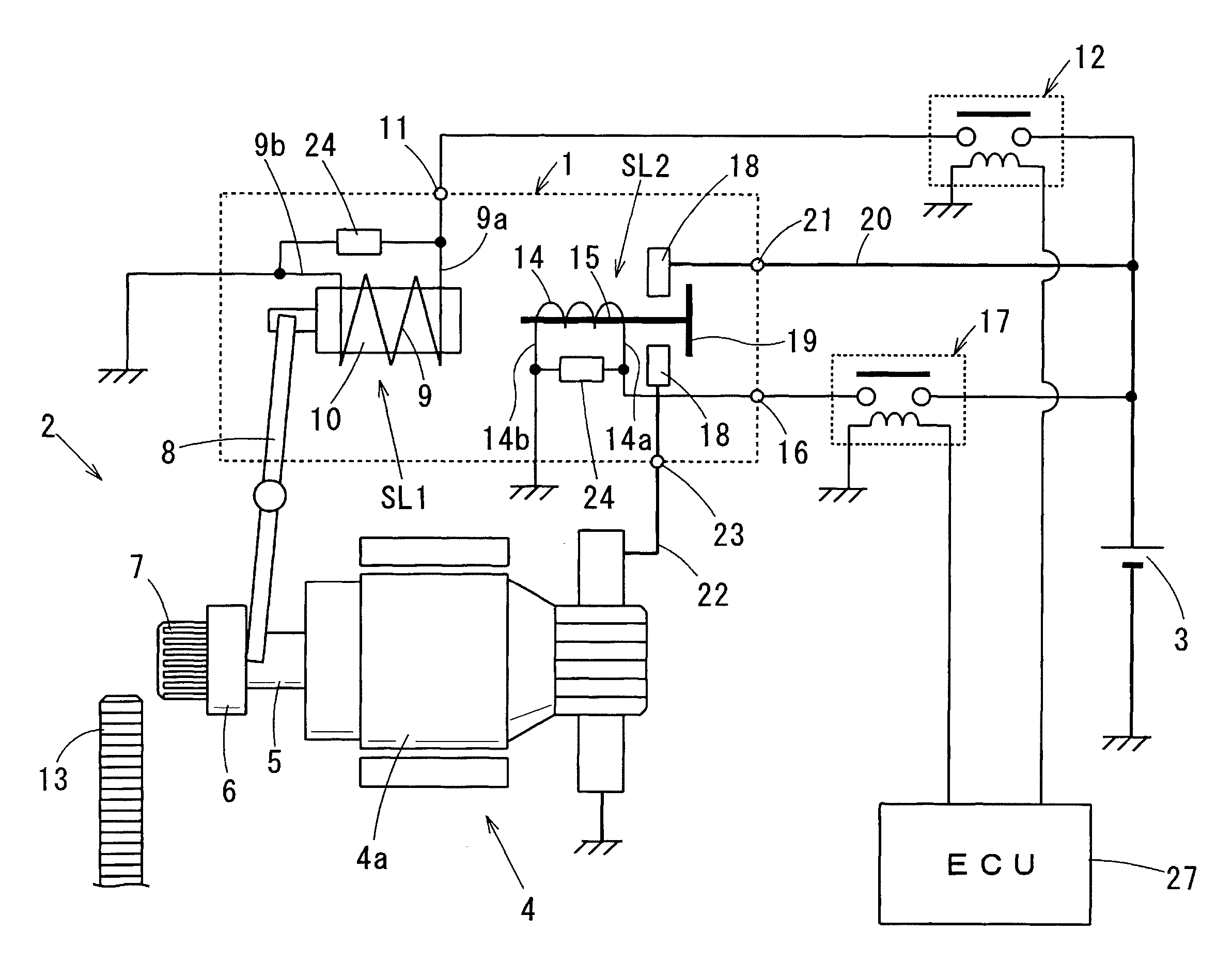
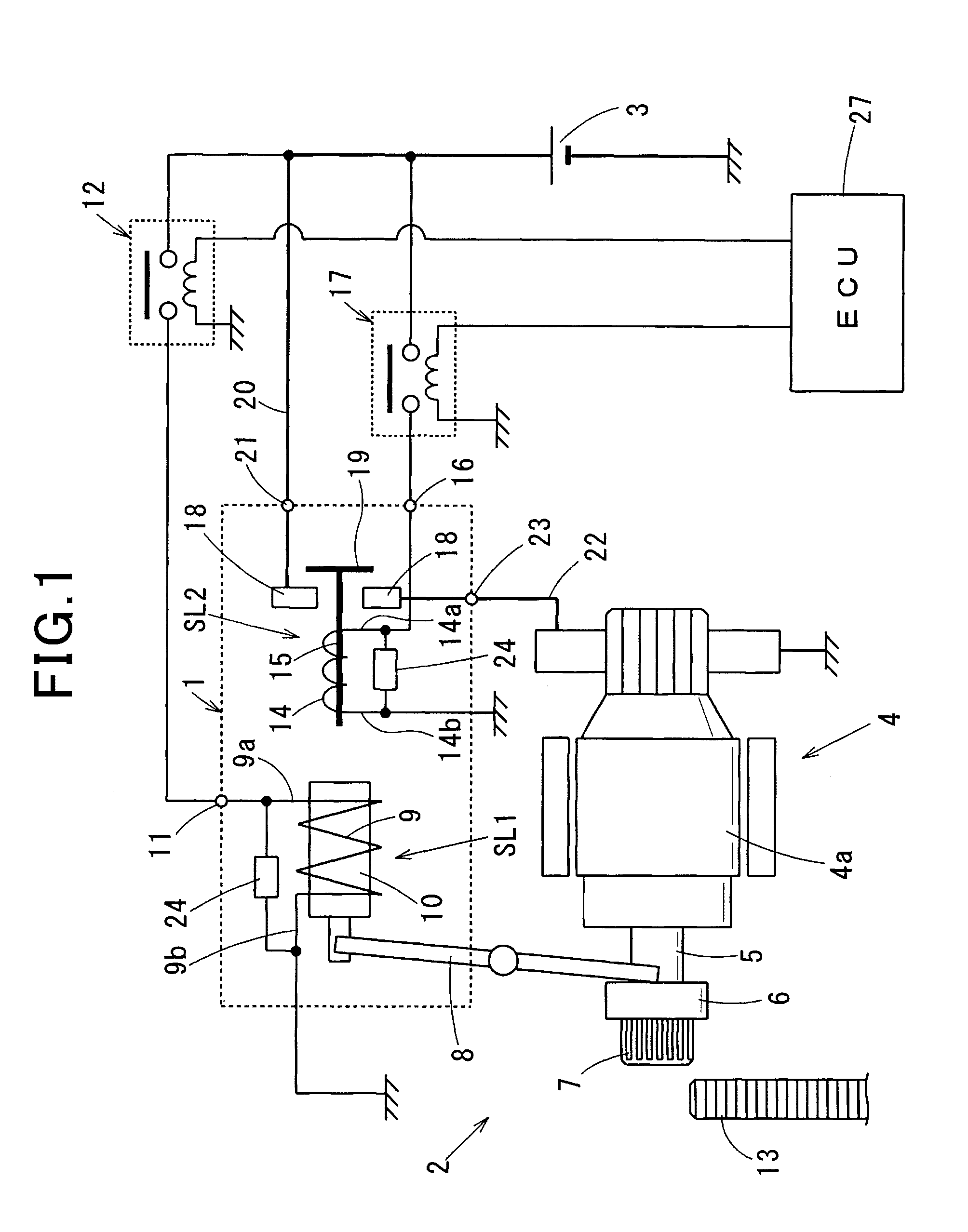
[0044]The surge suppression device 24 according to a second example is constituted of a resistor 28 connected in parallel to the SL1 coil 9 or the SL2 coil SL14 between the power supply side and the ground side as shown in FIG. 5. When the SL1 relay 12 or the SL2 relay 17 is turned from on to off, a current due to a counter-electromotive force generated across the SL1 coil 9 or the SL2 coil 14 circulates through the resistor 28 and the SL1 coil 9 or the SL2 coil 14. This circulation current can be adjusted by adjusting the resistance of the resistor 28.
[0045]Accordingly, part of the energy emitted from the SL1 coil 9 or the SL2 coil 14 is consumed by the resistor 28, and the remaining part of the energy is applied to the SL1 relay 12 or the SL2 relay 17. As a result, as shown in FIG. 6, adequate current flows between the contacts of the SL1 relay 12 or the SL2 relay 17, the contact surfaces can be cleaned. Incidentally, in this example shown in FIG. 5, a dark current flows through the
third example
[0046]The surge suppression device 24 according to a third example is constituted of a series connection of a resistor 28 and a diode 25. As shown in FIG. 7, the anode of the diode 25 is connected to one end of the resistor 28, the cathode of the diode 25 is connected to the power supply side of the SL1 coil 9 or the SL2 coil 14, and the other end of the resistor 28 is connected to the ground side of the SL1 coil 9 or the SL2 coil 14. FIG. 8 shows a modification of the surge suppression device 24 according to the third embodiment. In this modification, the diode 25 is disposed on the ground side and the resistor 28 is disposed on the power supply side in contrast to the example shown in FIG. 7. Specifically, the cathode of the diode 25 is connected to one end of the resistor 28, the anode of the diode 25 is connected to the ground side of the SL1 coil 9 or the SL2 coil 14, and the other end of the resistor 28 is connected the power supply side of the SL1 coil 9 or the SL2 coil 14. Like
fourth example
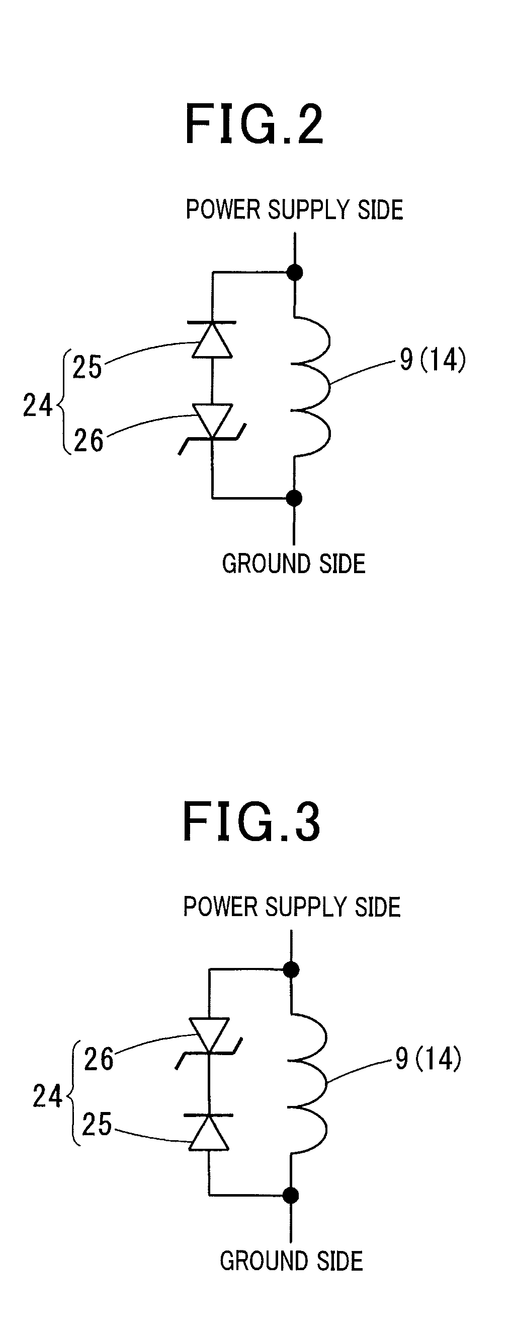
[0048]The surge suppression device 24 according to a fourth example is constituted of a first Zener diode 26a and a second Zener diode 26b connected in series as shown in FIG. 10. Specifically, the anodes of the first and second Zener diodes 26a and 26b are connected to each other, the cathode of the first Zener diode 26a is connected to the power supply side of the SL1 coil 9 or the SL2 coil 14, and the cathode of the second Zener diode 26b is connected to the ground side of the SL1 coil 9 or the SL2 coil 14.
[0049]FIG. 11 shows a modification of the surge suppression device 24 according to the fourth embodiment. In this modification, the first Zener diode 26a is disposed on the ground side, and the second Zener diode 26b is disposed on the power supply side in contrast to the example shown in FIG. 10. Specifically, the cathodes of the first and second Zener diodes 26a and 26b are connected to each other, the anode of the first Zener diode 26a is connected to the ground side of the SL1
PUM
 Abstract
Description
Claims
Application Information
 - R&D Engineer
- R&D Manager
- IP Professional
- Industry Leading Data Capabilities
- Powerful AI technology
- Patent DNA Extraction
Browse by: Latest US Patents, China's latest patents, Technical Efficacy Thesaurus, Application Domain, Technology Topic.
© 2024 PatSnap. All rights reserved.Legal|Privacy policy|Modern Slavery Act Transparency Statement|Sitemap


