Fiber-reinforced resin laminate

Inactive Publication Date: 2016-10-13
MITSUBISHI CHEM CORP
View PDF3 Cites 2 Cited by
  • Summary
  • Abstract
  • Description
  • Claims
  • Application Information

AI Technical Summary

Benefits of technology

[0038]According to the present invention, a fiber-reinforced resin laminate which has excellent mechanical characteristics applicable to structural materials, with less variation in the mechanical characteristics, and has excellent shapeability into complicated shapes, and which is inexpensive and enables molding in a short period of time, can be obtained.

Problems solved by technology

However, since the reinforcing fibers are continuous reinforcing fibers, the reinforcing fibers have low fluidity, and therefore, it is difficult to form a complicated shape such as a three-dimensional shape.
Thus, the applications of fiber-reinforced resins are limited mainly to members having a shape close to a planar shape.
However, since LFT-D causes unevenness in the fiber length or unevenness in the fiber distribution during the cutting and dispersing processes, there is a problem that the mechanical properties are deteriorated, or values of those properties vary widely.
However, although these base materials have superior mechanical characteristics and smaller variations of the characteristics compared to LFT-D, these base materials are not considered to have sufficient strength in order to be applied as structural materials.
Furthermore, in regard to Patent Document 3, the base material has sufficient strength that is appropriate for a structural material; however, the material requires a long molding cycle and has a problem with mass productivity.
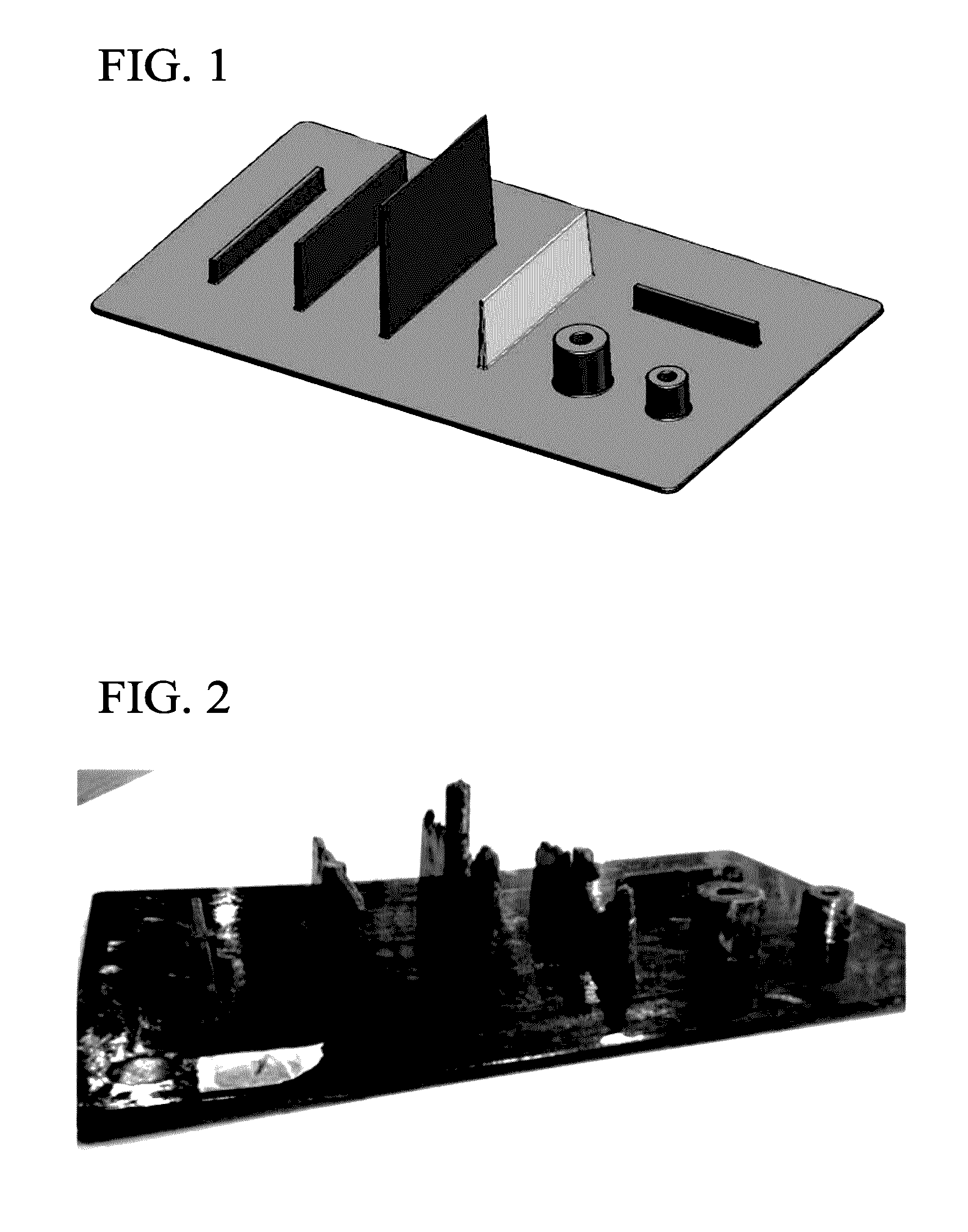
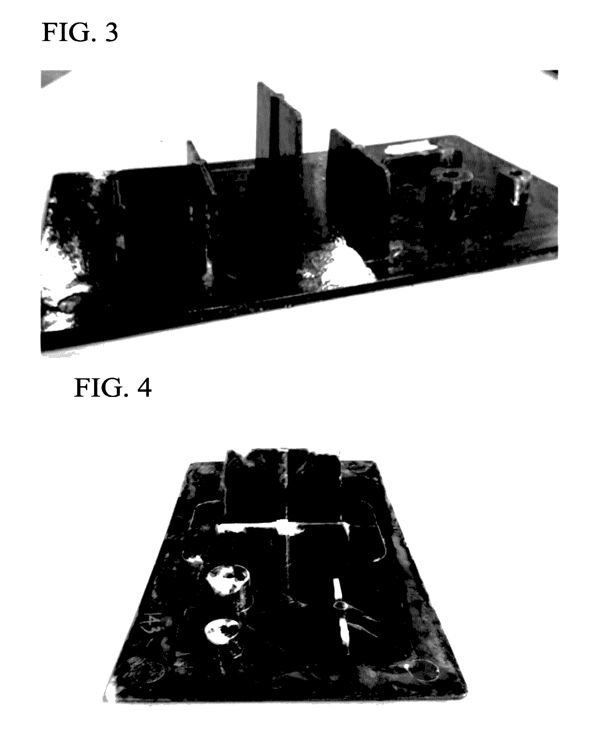
According to this method, amelioration in the mechanical characteristics and variations thereof can be achieved; however, since the material has insufficient stamping moldability, the material has a problem of poor shapeability into three-dimensional shapes such as ribs and hubs.

Method used


Image

  • Fiber-reinforced resin laminate
  • Fiber-reinforced resin laminate
  • Fiber-reinforced resin laminate

Examples


Example

Example 1

Production of Prepreg

[0151]Carbon fibers (manufactured by Mitsubishi Rayon Co., Ltd., product name: PYROFILL TR-50S15L) were aligned in a planar form such that the direction of the reinforcing fibers was unidirectional, and thus a reinforcing fiber sheet having a basis weight of 72.0 g / m2 was produced. Both surfaces of this reinforcing fiber sheet were interposed between films of nylon 6 (nylon 6; manufactured by Ube Industries, Ltd., product name: 1013B, melting point: 218° C., thickness: 40 μm), and the reinforcing fiber sheet was impregnated with the thermoplastic resin by passing the assembly several times between calendar rolls. Thus, a prepreg having a carbon fiber volume percentage content (Vf) of 34% and a thickness of 0.125 mm was obtained.

[0152](Production of Fiber-Reinforced Resin Laminate)

[0153]The prepreg thus obtained was cut into a size of 300 mm on each side, and incisions were inserted therein at a constant interval as indicated in Table 1, using a sample cu

Example

Example 2

[0156]A fiber-reinforced resin laminate was produced in the same manner as in Example 1, except that incision processing at an angle θ formed by an incision that cut the fibers and a reinforcing fiber of 30° was performed such that the carbon fibers had a constant length (average fiber length) L of 25.0 mm and an average cutting length l of 20 mm. An evaluation of the laminate was performed. The sum total of the cutting length, la, per 1 m2 of the PPG used at the surface layer at this time was 80 m.

Example

Example 3

[0157]A fiber-reinforced resin laminate was produced in the same manner as in Example 1, except that the PPG and a nylon 6 sheet (nylon 6; manufactured by Ube Industries, Ltd., product name: 1013B) having a thickness of 1 mm were superposed as indicated in Table 1, and an evaluation of the laminate was performed. The sum total of the cutting length, la, per 1 m2 of the PPG used at the surface layer at this time was 56.6 in.


PUM

PropertyMeasurementUnit
Fractionaaaaaaaaaa
Fractionaaaaaaaaaa
Angleaaaaaaaaaa

Abstract

Provided is a fiber-reinforced resin laminate that is characterized by: comprising stacked layers of the (A) layer and the (B) layer that are indicated below; and by the value resulting from dividing the sum total of the thickness of the (A) layer by the sum total of the thickness of the (B) layer being 0.5-3.0. (A) layer: a laminate that comprises a prepreg in which reinforcing fibers are impregnated with a resin or a resin composition and wherein the product of the square of the volume fraction (Vf) of the reinforcing fibers and the average fiber length (Lamm) is greater than 2.0 mm and equal to or less than 15 mm. (B) layer: a sheet that comprises at least one composition selected from the group consisting of resin compositions and filler-containing resin compositions and wherein the product of the square of the volume fraction (Vf) of the filler and the average value (Lbmm) of the maximum length of the filler is 2.0 mm or less.

Description


Claims


Application Information

Patent Timeline
Owner MITSUBISHI CHEM CORP
Why Eureka
Try Eureka