Polarizing plate with optical compensation layer and organic el panel using same
- Summary
- Abstract
- Description
- Claims
- Application Information
AI Technical Summary
Benefits of technology
Problems solved by technology
Method used
Image

Examples
Example
Example 1
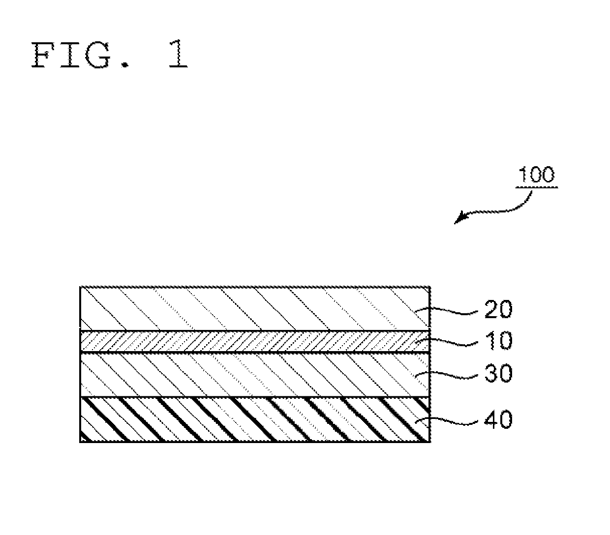
[0081](i) Production of First Optical Compensation Layer
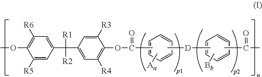
[0082](i-1) Synthesis of Polyarylate
[0083]27.0 kg of 2,2-bis (4-hydroxyphenyl) -4-methylpentane and 0.8 kg of tetrabutylammonium chloride were dissolved in 250 L of a sodium hydroxide solution in a reaction vessel equipped with a stirring apparatus. To the stirred solution, a solution obtained by dissolving 13.5 kg of terephthaloyl chloride and 6.30 kg of isophthaloyl chloride in 300 L of toluene was added all at once, followed by stirring at room temperature for 90 minutes. Thus, a polycondensation solution was obtained. After that, the polycondensation solution was separated by being left to stand still to separate a toluene solution containing polyarylate. Next, the separated liquid was washed with aqueous acetic acid and further washed with ion-exchanged water. After that, the washed product was loaded into methanol to precipitate the polyarylate. The precipitated polyarylate was filtered and dried under reduced press
Example
Example 2
[0101]A polarizing plate with optical compensation, layers having the configuration “protective layer / polarizer / first optical compensation layer / second optical compensation layer” was obtained in the same manner as in Example 1 except that: a retardation film of a polycarbonate-based resin obtained as described below was used as the first optical compensation layer; and the polarizer and the first optical compensation layer were bonded to each other so that the absorption axis of the polarizer and the slow axis of the first optical compensation layer were substantially parallel to each other Further, an organic EL panel was produced in the same manner as in Example 1 except that the polarizing plate with optical compensation layers was used. The polarizing plate with optical compensation layers and the organic EL panel thus obtained were subjected to the same evaluations as those of Example 1. The results are shown in Table 1.
[0102]Phosgene serving as a carbonate precurs
Example
Example 3
[0104]A polarizing plate with optical compensation layers having the configuration “protective layer / polarizer / first optical compensation layer / second optical compensation layer” was obtained in the same manner as in Example 1 except that a retardation film of a cellulose acetate resin obtained as described below was used as the second optical compensation layer. Further, an organic EL panel was produced in the same manner as in Example 1 except that the polarizing plate with optical compensation layers was used. The polarizing plate with optical compensation layers and the organic EL panel thus obtained were subjected to the same evaluations as those of Example 1. The results are shown in Table 1.
[0105]Shrinkable films having the same size (biaxially stretched films of PP, thickness: 60 μm) were bonded to both surfaces of a cellulose acetate resin film (220×120 mm, thickness: 50 μm) with acrylic pressure-sensitive adhesives. Thus, a laminate was obtained. After that, th
PUM
 Abstract
Description
Claims
Application Information
 - R&D Engineer
- R&D Manager
- IP Professional
- Industry Leading Data Capabilities
- Powerful AI technology
- Patent DNA Extraction
Browse by: Latest US Patents, China's latest patents, Technical Efficacy Thesaurus, Application Domain, Technology Topic.
© 2024 PatSnap. All rights reserved.Legal|Privacy policy|Modern Slavery Act Transparency Statement|Sitemap