Purification apparatus for compressed air

a technology of purification apparatus and compressed air, which is applied in the direction of vortex flow apparatus, cleaning equipment, separation process, etc., can solve the problems of increased contamination, reduced efficiency of separating oil and foreign substances, and increased contamination, so as to achieve the effect of maximizing air purification efficiency, reducing the efficiency of separating oil and foreign substances, and greatly accelerating the second swirling of compressed air

Active Publication Date: 2017-03-30
LEE SANG PHIL
View PDF13 Cites 4 Cited by
  • Summary
  • Abstract
  • Description
  • Claims
  • Application Information

AI Technical Summary

Benefits of technology

This patent describes a device called a cyclone generator that generates two cyclones with different sizes. One larger cyclone captures more compressed air than other smaller ones, causing it to rotate faster. Another smaller cyclone capturing lesser amounts of compressed air compared to older devices. By rotating these cyclones together, the device effectively separates oil from particles. It also improves air purification because the compressed air does not pass through filters before entering the cyclone chamber. Additionally, the device uses multiple channels on the outside of the outer drum to efficiently separate small water or oil particles, increasing their effectiveness. Overall, this technology allows for efficient separation of oil and harmful materials in industrial settings.

Problems solved by technology

The technical problem addressed in this patent text relates to improving the purification of compressed air by separating moisture and impurities from the compressed air without requiring frequent replacement of filters. Existing methods involve filtering the entirety of the compressed air using filters, which requires periodic cleanings and replacements. Additionally, existing methods have limitations in terms of efficient operation and effective separation of small amounts of moisture and impurities.

Method used


Image

  • Purification apparatus for compressed air
  • Purification apparatus for compressed air
  • Purification apparatus for compressed air

Examples


Embodiment Construction

[0036]Certain embodiments of the present invention are described below with reference to the accompanying drawings.

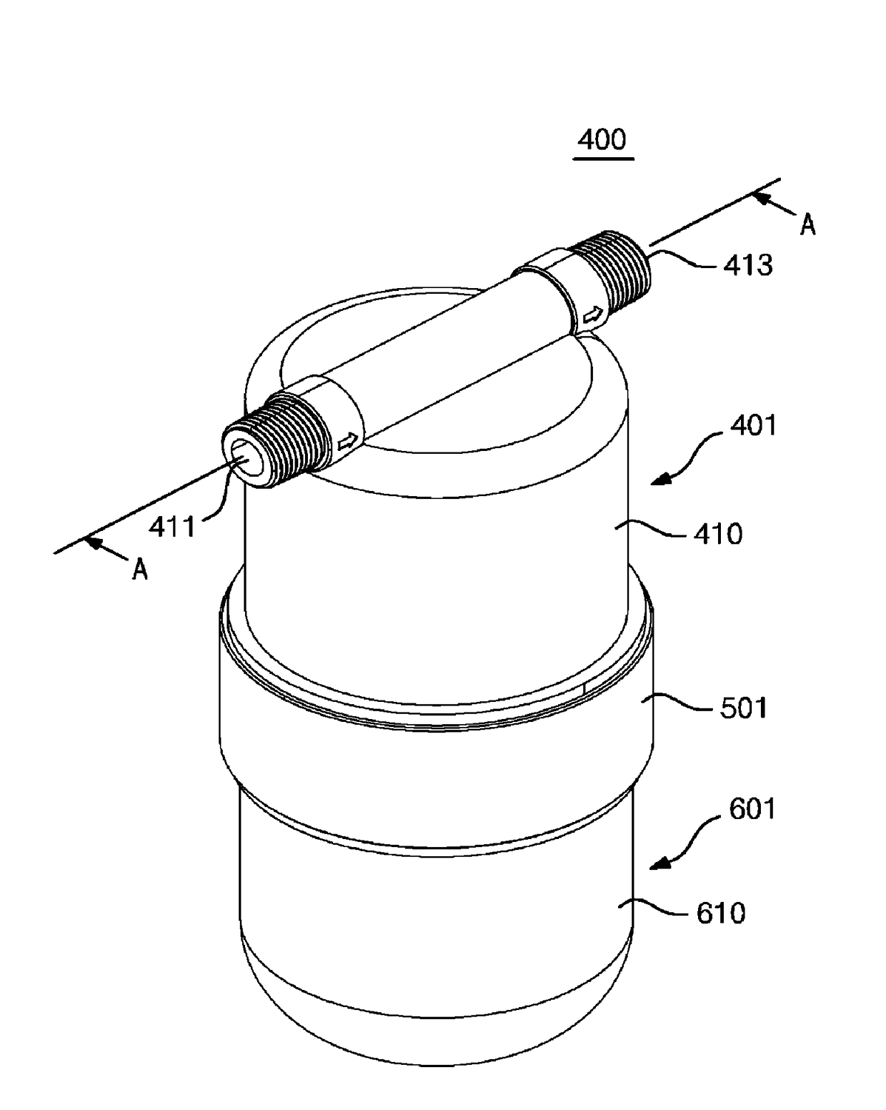
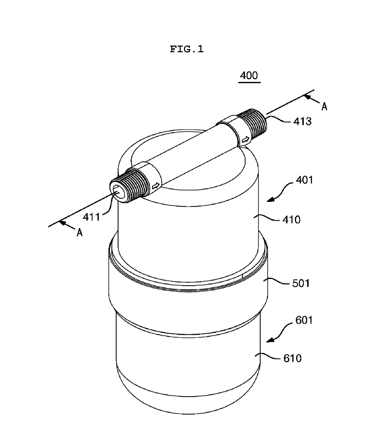
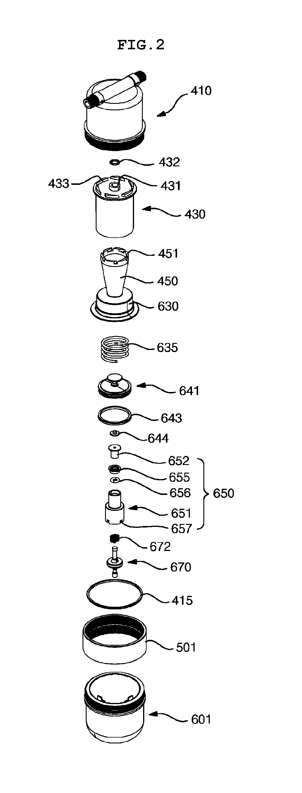
[0037]FIG. 1 is a perspective view of a compressed air purification apparatus according to an embodiment of the present invention, FIG. 2 is an exploded perspective view of FIG. 1, FIG. 3 is a perspective view of the inner drum and the collector drum, FIG. 4 is a cross-sectional view across A-A of FIG. 1, FIG. 5 is a cross-sectional view across B-B of FIG. 4, FIG. 6 is a cross-sectional view across C-C of FIG. 4, FIG. 7a is a cross-sectional view illustrating an operating state of the drain member (compressor OFF, pneumatic device OFF), FIG. 7b is a cross-sectional view illustrating an operating state of the drain member (compressor ON, pneumatic device OFF), and FIG. 7c is a cross-sectional view illustrating an operating state of the drain member (compressor ON, pneumatic device ON).

[0038]As illustrated in FIGS. 1 to 7c, a compressed air purification apparatus 400 accordi


PUM

PropertyMeasurementUnit
Pressureaaaaaaaaaa
Diameteraaaaaaaaaa
Perimeteraaaaaaaaaa

Abstract

A compressed air purification apparatus includes a cover, an outer drum configured such that compressed air supplied through the inlet swirls downwards between the cover and the outer drum, a discharge pipe inserted into the insertion port to couple the outer drum to the cover, an inner drum configured such that the downwardly swirling compressed air flows upwards between the outer drum and the inner drum and again swirls downwards between the discharge pipe and the inner drum, a collector drum formed in an integrated manner with the inner drum, and a drain cover configured such that impurities separated from the compressed air are collected therein. The compressed air can separate water, oil and minute foreign substances from compressed air by rotating compressed air two times in a double cyclone.

Description


Claims


Application Information

Patent Timeline
Owner LEE SANG PHIL
Why Eureka
Try Eureka