Double-cyclone urea mixing device

A swirl mixing and mixing device technology, which is applied in the direction of muffler, exhaust device, exhaust treatment, etc., can solve the problems of insufficient mixing of tail gas and ammonia gas and incomplete tail gas treatment, so as to ensure the effect of tail gas treatment and improve Gas mixing efficiency, effect of saving mixing time

Inactive Publication Date: 2019-10-25
WUXI WEIFU LIDA CATALYTIC CONVERTER
View PDF7 Cites 3 Cited by
  • Summary
  • Abstract
  • Description
  • Claims
  • Application Information

AI Technical Summary

Benefits of technology

This technology allows for complete mixture between urea (NH2) and exhaust gases without having long waiting times or requiring complicated equipment like air separation systems that are expensive. It also improves the effectiveness of treating these harmful emissions by efficiently breaking down them into smaller molecules with less pollution than traditional methods.

Problems solved by technology

This patented method for improving the efficiency at which an SCR device removes NOX from vehicle emissions involves injecting urease liquid onto the tailpipe or flue gases passing by them. However, this approach may result in poor mixing between these two types of fluid due to their different temperatures when reacted together.

Method used


Image

  • Double-cyclone urea mixing device

Examples


Embodiment Construction

[0013] The present invention will be further described below in conjunction with specific examples.

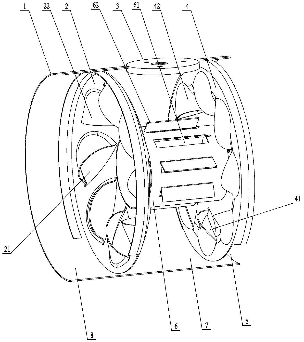
[0014] The double-swirl urea mixing device of the present invention includes a mixing cylinder 1, a front swirl partition 2, a spray base 3, a rear swirl partition 4 and a swirl mixing tube 6; fixed on the wall of the mixing cylinder 1 There is a spray base 3, and the front swirl partition 2 and the rear swirl partition 4 are fixed in the mixing cylinder 1. The front end of the swirl mixing tube 6 is fixed with the front swirl partition 2, and the swirl mixing The rear end of the tube 6 is fixed to the rear swirl partition 4;

[0015] A front swirl flow hole 21 is opened on the front swirl flow partition 2 between the swirl flow mixing tube 6 and the mixing cylinder 1, and on the front wall surface of the front swirl flow partition 2 corresponding to each front swirl flow hole 21 The front swirl ear 22 is fixed;

[0016] On the back swirl baffle 4 between the swirl mixing tube


PUM

PropertyMeasurementUnit
Lengthaaaaaaaaaa
Widthaaaaaaaaaa

Abstract

The invention relates to a double-cyclone urea mixing device. The wall of a mixing cylinder is fixed with an injection base, and a front cyclone partition plate and a rear cyclone partition plate arefixed in the mixing cylinder; the front end part of a cyclone mixing pipe is fixed with the front cyclone partition plate, and the rear end part of the cyclone mixing pipe is fixed with the rear cyclone partition plate; front cyclone holes are formed in the front cyclone partition plate between the cyclone mixing pipe and the mixing cylinder, and front cyclone lugs are fixed on the front wall surface of the front cyclone partition plate corresponding to the positions of the front cyclone holes; rear cyclone holes are formed in the rear cyclone partition plate between the cyclone mixing pipe and the mixing cylinder, and rear cyclone lugs are fixed on the front wall surface of the rear cyclone partition plate corresponding to the positions of the rear cyclone holes; and the cyclone mixing pipe is provided with a flow guide opening, and a flow guide fin is fixed on the excircle of the cyclone mixing pipe corresponding to the position of the flow guide opening. The invention has the advantages of ingenious and efficient structure, full mixing of ammonia gas and tail gas, mixing time saving, great improvement of gas mixing efficiency and guarantee of tail gas treatment effect.

Description


Claims


Application Information

Patent Timeline
Owner WUXI WEIFU LIDA CATALYTIC CONVERTER
Why Eureka
Try Eureka