Cleaning equipment and cleaning method of deposition mask

a deposition mask and cleaning equipment technology, applied in the direction of cleaning using liquids, vacuum evaporation coatings, coatings, etc., can solve the problems of difficult collection and recycling of deposition agents, and achieve the effect of enhancing the usability of adhesive agents and improving the usability of masks

Inactive Publication Date: 2010-04-29
HITACHI HIGH-TECH CORP
View PDF1 Cites 2 Cited by
  • Summary
  • Abstract
  • Description
  • Claims
  • Application Information

AI Technical Summary

Benefits of technology

In this patented technology there are two main technical features: firstly, how to reuse or recover collected deposition agents during manufacturing processes; secondly, where they can get mixed up when reused after being captured onto certain parts inside the machine's vacuum chambers (vacuums).

Problems solved by technology

Technological Problem: Current methods used for removing photochemistry materials are limited due to their tendency towards being damaged during removal process steps that require long periods of exposure. Dry processes involving UV lamps can provide higher efficiency but they often result in contamination issues. Liquid phase separation techniques involve evaporation/sublimation reactions between different components within the material, resulting in poor quality images.

Method used


Image

  • Cleaning equipment and cleaning method of deposition mask
  • Cleaning equipment and cleaning method of deposition mask
  • Cleaning equipment and cleaning method of deposition mask

Examples


first embodiment

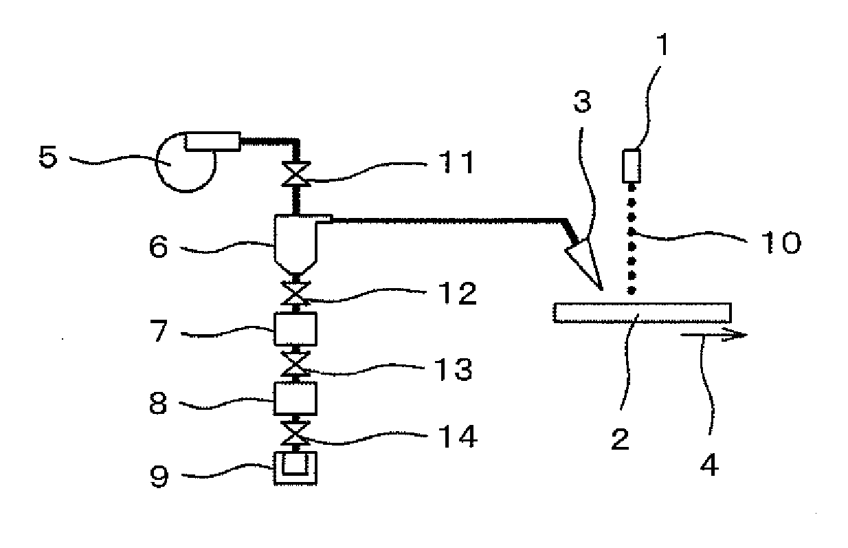
[0040]The present invention will be described referring to the drawings. FIG. 1 shows a basic structure of the present invention. A pulse laser 10 is irradiated from a laser irradiation window 1 to a deposition mask 2 as a target to be cleaned. The deposition mask 2 has been used for the deposition repeatedly, which needs to be cleaned. The frequency of the pulse laser is substantially long relative to the pulse width. The pulse laser is irradiated to the deposition mask 2 to be oscillated such that the deposition agent adhered to the deposition mask 2 is separated.

[0041]The deposition mask 2 moves along an advancing direction 4. The pulse laser 10 is controlled to scan vertically to the advancing direction 4. The advancement of the deposition mask 2 and the scan of the pulse laser 10 are combined so as to irradiate the pulse laser 10 to the entire surface of the deposition mask.

[0042]The deposition agent separated by the pulse laser is sucked by a suction nozzle 3 into a cyclone 6 tog

second embodiment

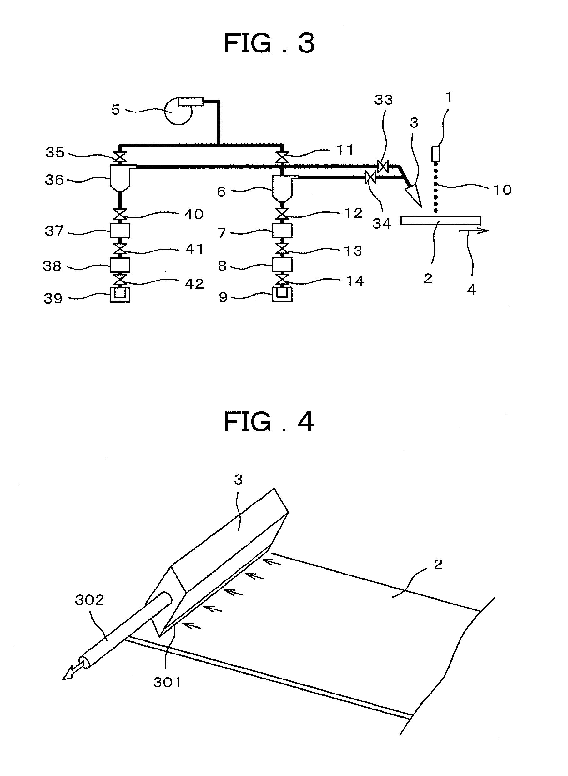
[0065]An example where two kinds of deposition masks 2, that is, the one subjected to 200-hour deposition using the deposition agent Alq3 (tris(8-quinolinolate)aluminum derivative), and the one subjected to 200-hour deposition using the deposition agent BeBq(bis(benzoquinolinolate)beryllium derivative) will be described hereinafter. FIG. 3 shows the structure of the device, which is formed by adding one more collection section to the basic structure shown in FIG. 1 to allow processing of two kinds of the deposition masks 2. The deposition mask 2 is cleaned using Alq3. The valves F34 and A11 are opened, and valves E33 and G35 are closed to activate the blower 5. The deposition mask 2 is transferred along the advancing direction 4 while irradiating the pulse laser 1. When the cleaning of the deposition mask 2 using Alq3 is finished, the valves F34 and A11 are closed, and the valves E33 and G35 are opened to process the deposition mask 2 using BeBq. The process for collecting the depositi


PUM

PropertyMeasurementUnit
Efficiencyaaaaaaaaaa

Abstract

Equipment is realized which is capable of increasing the frequency of use of a deposition mask of an organic EL element and the recycle of an adhesive agent by efficiently cleaning the deposition mask with little damage and efficiently collecting the adhesive agent. A pulse laser is irradiated to a deposition mask to separate the deposition agent from the deposition mask. The separated deposition agent is sucked by a suction nozzle, and the deposition agent is separated from air by a cyclone and deposited on a bottom of the cyclone. Thereafter, a first valve is opened to collect the deposition agent in a deposition agent collection section. Then a second valve is opened to move the deposition agent to a deposition agent refining section to be refined. A third valve is opened to store the refined deposition agent in a deposition agent storage section. The deposition mask may be cleaned without being damaged to collect the deposition agent with high efficiency.

Description


Claims


Application Information

Patent Timeline
Owner HITACHI HIGH-TECH CORP
Why Eureka
Try Eureka