Plasma source utilizing a macro-particle reduction coating and method of using a plasma source utilizing a macro-particle reduction coating for deposition of thin film coatings and modification of surfaces

Active Publication Date: 2017-11-23
AGC FLAT GLASS NORTH AMERICA INC +2
View PDF5 Cites 2 Cited by
  • Summary
  • Abstract
  • Description
  • Claims
  • Application Information

AI Technical Summary

Benefits of technology

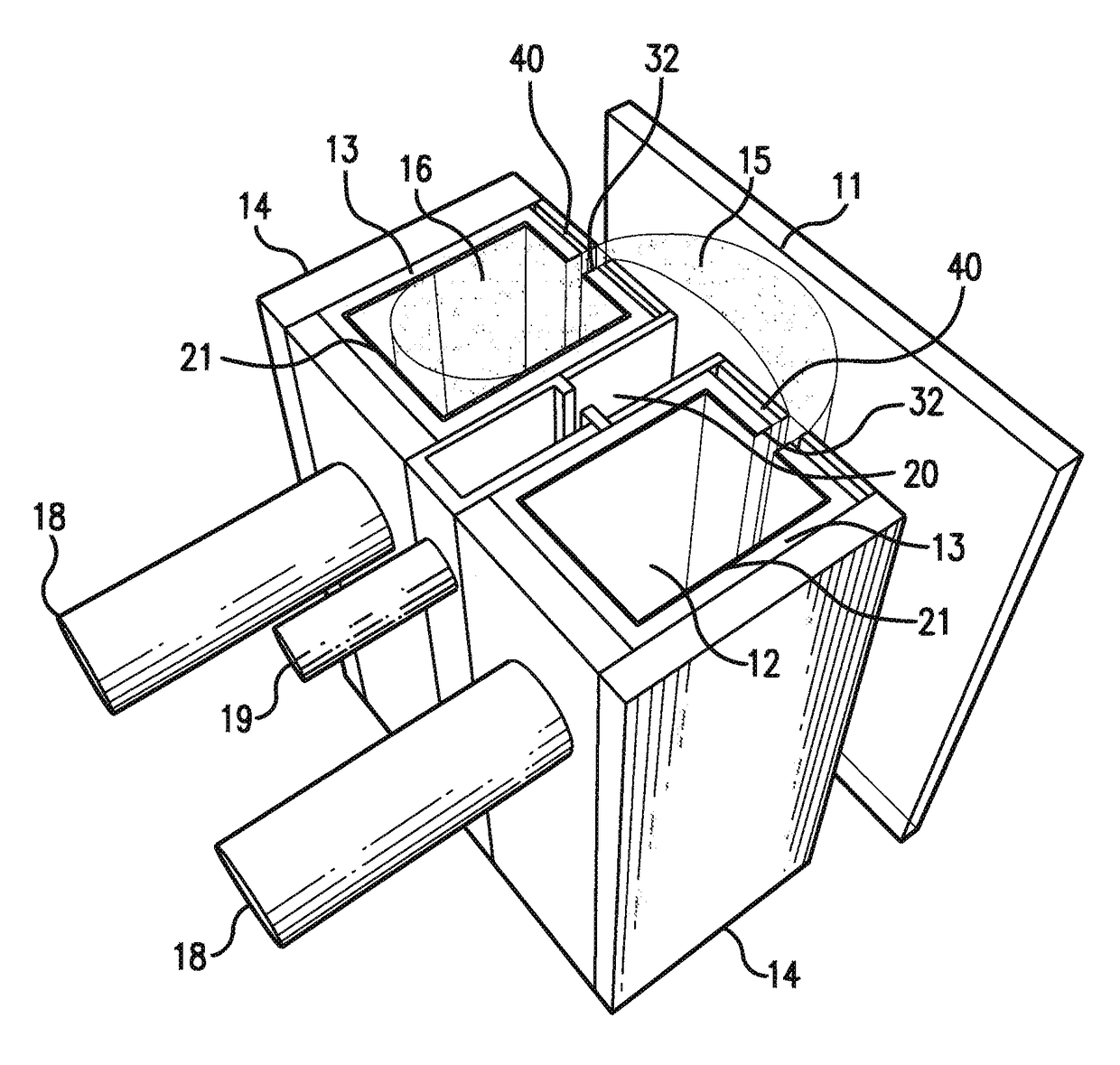
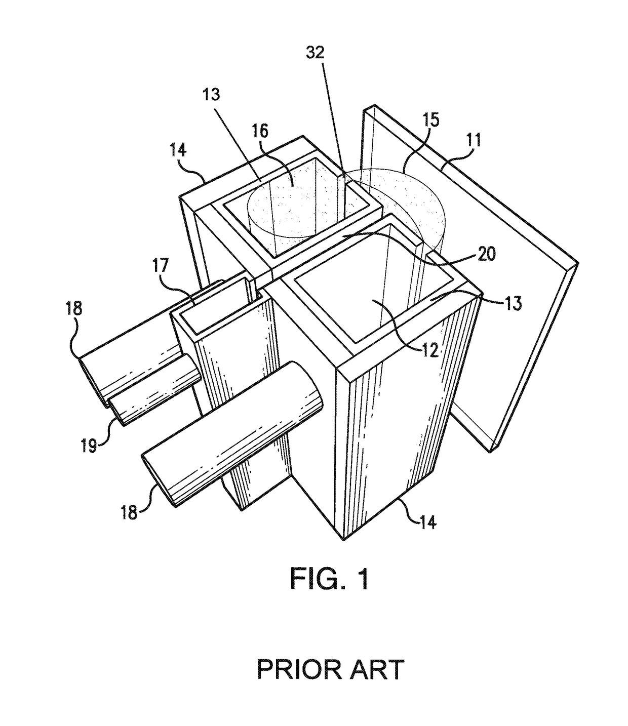
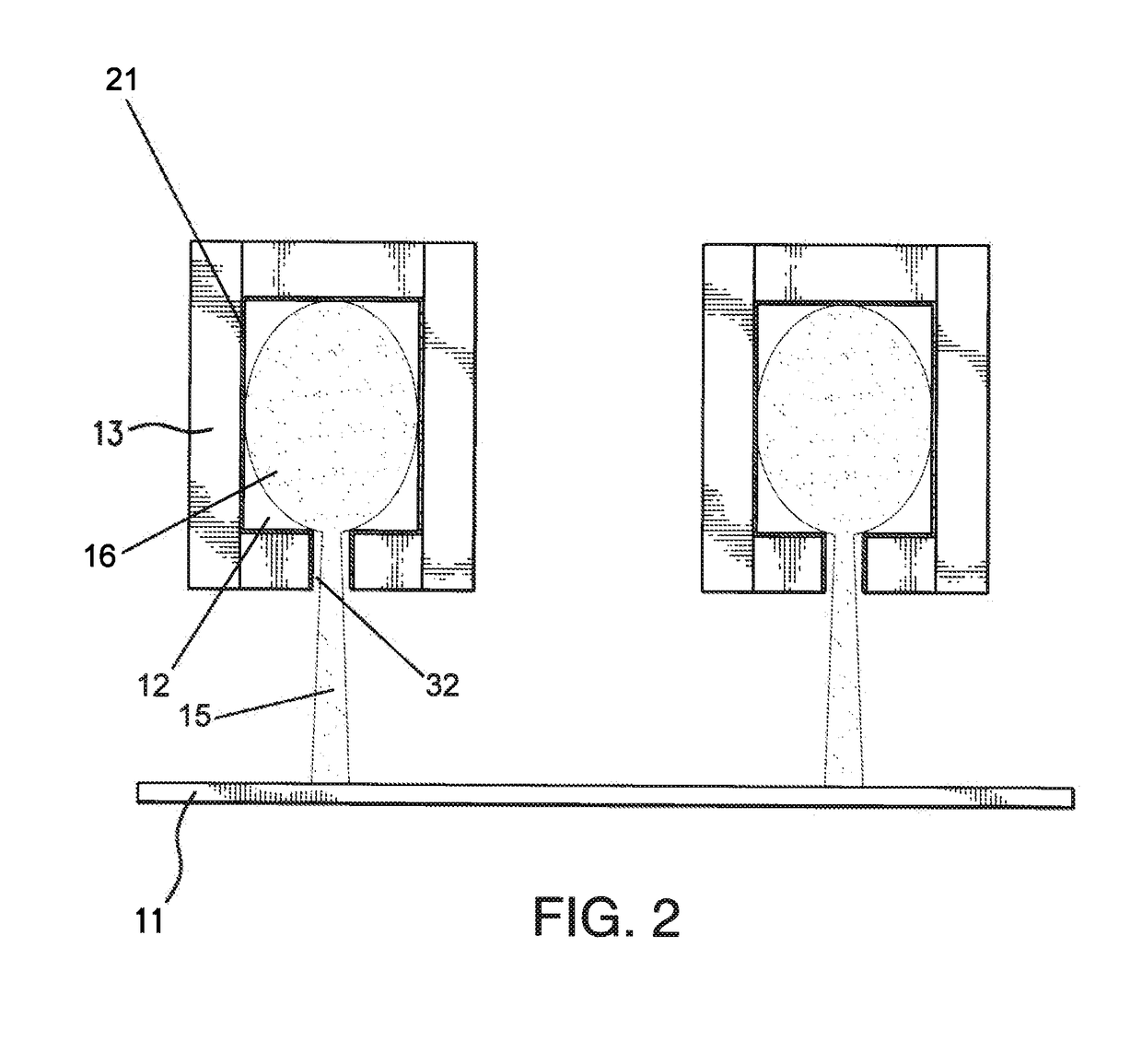
[0023]The plasma source, in some embodiments of the invention, may be configured to deposit a coating using plasma enhanced chemical vapor deposition (PECVD). When configured for PECVD, a gas inlet configured to supply a precursor gas and a gas inlet configured to supply a plasma gas are included. The precursor gas is activated by the plasma. A substrate is conveyed adjacent to the source, and a thin film is deposited on the substrate from the activated gas. The inventors of the subject matter described herein have found that when incorporated into a plasma source, electrodes coated at least partially with the macro-particle reduction coatings disclosed herein serve to improve the function of and increase the service life of the plasma source, while also providing numerous additional benefits. These benefits include: 1) greatly reduced sputter erosion of the electrodes; 2) extension of the source service life; 3) enhanced process performance; 4) stabilized voltage output.

Problems solved by technology

Sputtering of the electrode material within a plasma source is a significant problem encountered during the use of many known plasma sources.
Electrode sputtering is a particularly significant problem in the field of glass coating, which requires continuous operation of the plasma sources for 100 to 600 hours, above a substrate undergoing a process which is very sensitive to the presence of foreign particles.
Electrode sputtering during extended plasma source operation results in reduced service life of the electrodes.
The redeposition of the sputtered material may also lead to blockage of the nozzles of the plasma source, making a uniform substrate treatment or coating impossible.
Furthermore, depending on the electrode material and the plasma-forming gas, the sputtering of the electrode may lead to the formation of particulate debris.
The debris may further block the source's nozzles, or fall on the substrate creating defects.

Method used


Image

  • Plasma source utilizing a macro-particle reduction coating and method of using a plasma source utilizing a macro-particle reduction coating for deposition of thin film coatings and modification of surfaces
  • Plasma source utilizing a macro-particle reduction coating and method of using a plasma source utilizing a macro-particle reduction coating for deposition of thin film coatings and modification of surfaces
  • Plasma source utilizing a macro-particle reduction coating and method of using a plasma source utilizing a macro-particle reduction coating for deposition of thin film coatings and modification of surfaces

Examples


Example

Example 1

Macro-Particle Reduction Coatings Reduce Macro-Particle Accumulation on a Substrate During Extended Plasma Source Operation

[0085]The inventors sought to determine the ability of the macro-particle reduction coatings of the instant invention to reduce macro-particle formation on a substrate during extended plasma source operation. A first test was performed using a hollow cathode plasma source comprising two uncoated stainless steel electrodes (“2kw Plain SS”). These electrodes were arranged substantially parallel to one another, and the distance between the centers of each hollow cathode cavity was 116 mm. The plasma length was 100 mm, measured along the length of each electrode, i.e. between the centers of the furthest plasma nozzles of each electrode. The plasma source was positioned over a ceramic substrate and used to generate a plasma for a run time of approximately 160 hours. This test was repeated with a separate uncoated stainless steel electrode under the same conditi

Example

Example 2

Macro-Particle Reduction Coatings Reduce the Formation of Macro-Particles in the Interior Cavity of Hollow Cathode Electrodes During Extended Plasma Source Operation

[0089]The inventors sought to determine the ability of the macro-particle reduction coatings of the instant invention to reduce macro-particle formation in the interior cavity of hollow cathode electrodes during extended plasma source operation.

[0090]FIG. 6 shows the results of an experiment wherein hollow cathode electrodes were provided and configured in a plasma source. The internal cavity of the hollow cathodes, where plasma formation occurs, was either uncoated (Plain SS), or was coated with a tungsten carbide coating (WC Coated). The coating was approximately 100 μm thick, and comprised a 12% cobalt binder. The plasma sources were used to generate a plasma for a predetermined period of time greater than 100 hours. Specifically, the predetermined period of time was between 100-200 hours. After completion of th

Example

Example 3

Macro-Particle Reduction Coatings Stabilize Voltage Output During Extended Plasma Source Operation

[0092]The inventors sought to determine the ability of the macro-particle reduction coatings of the instant invention to reduce voltage drift of a plasma source during extended operation.

[0093]Output voltage was compared between a hollow cathode plasma source incorporating uncoated stainless steel electrodes and a similar hollow cathode plasma source incorporating electrodes coated with a macro-particle reduction coating, during extended operation of the plasma sources.

[0094]In the first test, a hollow cathode plasma source comprising two uncoated stainless steel electrodes were used to generate a plasma for a test run lasting at least 144 hours, at a power density of 20 kW / m. As shown in FIG. 7A, the operating voltage increased by approximately 20 volts over the course of the test run. When the power was increased to 40 kw / m in a similar test, the voltage increased by approxi


PUM

PropertyMeasurementUnit
Timeaaaaaaaaaa
Timeaaaaaaaaaa
Thicknessaaaaaaaaaa

Abstract

The present invention relates generally to a plasma source utilizing a macro-particle reduction coating and method of using a plasma source utilizing a macro-particle reduction for deposition of thin film coatings and modification of surfaces. More particularly, the present invention relates to a plasma source comprising one or more plasma-generating electrodes, wherein a macro-particle reduction coating is deposited on at least a portion of the plasma-generating surfaces of the one or more electrodes to shield the plasma-generating surfaces of the electrodes from erosion by the produced plasma and to resist the formation of particulate matter, thus enhancing the performance and extending the service life of the plasma source.

Description


Claims


Application Information

Patent Timeline
Owner AGC FLAT GLASS NORTH AMERICA INC
Why Eureka
Try Eureka