Belt edge

a belt edge and belt technology, applied in the field of belts, can solve the problems of affecting the shape of the belt, replacing more frequently, etc., and achieve the effect of reducing the tensile strength of the fused region so obtained and preventing the fraying of the edg

Inactive Publication Date: 2017-12-21
CLEAR EDGE GERMANY
View PDF10 Cites 1 Cited by
  • Summary
  • Abstract
  • Description
  • Claims
  • Application Information

AI Technical Summary

Benefits of technology

The technical effect of this patented process described by this patents relates to reducing tension on woven fabrics made from synthetic fibres while maintaining their mechanical integrity when they have been treated beforehand (fusion). This can lead to improved performance characteristics such as increased durability against wear-out caused by abrasions between different parts of the fabric) and reduced air leakage through filters that contain these materials.

Problems solved by technology

Technological Problem: Current Trip Press Filter Belt Seam Lead Edge Pluggage (LSP), especially if there were flaws caused by high stress levels experienced from repeated usage over time, can result in edge wornness leading to safety concerns and downtime issues associated with maintenance work. Additionally, current methods have limitations including thermal shrinking, excessive shedding, slipping between parts, etc., making them difficult to maintain consistency and reduce component life cycle costs.

Method used


Image

  • Belt edge

Examples


Embodiment Construction

[0054]In order that the invention may be more clearly understood an embodiment / embodiments thereof will now be described, by way of example only, with reference to the accompanying drawings, of which:

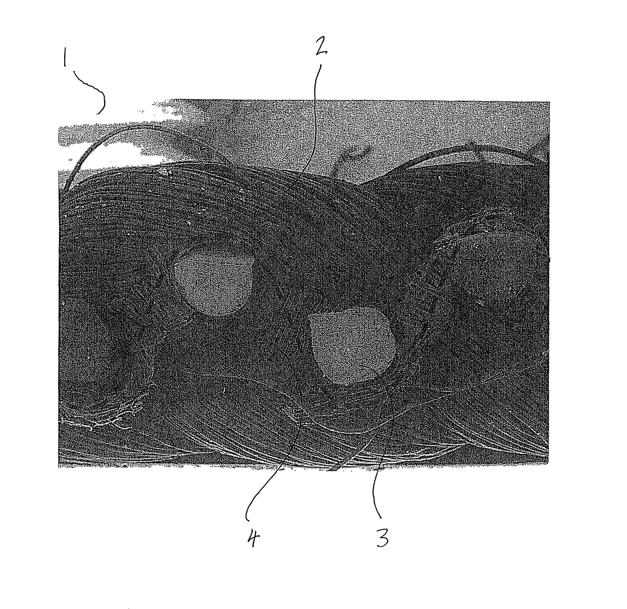
[0055]FIG. 1 shows a cross section of belt comprising warp yarns, weft yarns and a fused region formed from the warp yarn, the weft yarn and the yarn for fusing the warp and weft yarns.

[0056]The above embodiment is described by way of example only. Many variations are possible without departing from the scope of the invention.

[0057]FIG. 1 shows a cross section of a belt (1) comprising a plurality of interlocking warp yarns (2) and weft yarns (3). The warp yarns are longitudinal (i.e. they run in machine direction) and the weft yarns are woven through the warp yarns in a direction perpendicular to the machine direction. Further yarns (4) for fusing the warp yarns and the weft yarns are provided substantially parallel with the warp yarns (i.e. they also run in the machine direction) at eac


PUM

PropertyMeasurementUnit
Diameteraaaaaaaaaa
Diameteraaaaaaaaaa
Widthaaaaaaaaaa

Abstract

The present invention relates to a belt comprising a warp yarn and a weft yarn, wherein the belt comprises a fused region along each longitudinal edge of the belt, said fused region being formed from the warp yarn, the weft yarn and a yarn provided for fusing the warp yarn and the weft yarn together.

Description


Claims


Application Information

Patent Timeline
Owner CLEAR EDGE GERMANY
Why Eureka
Try Eureka