Parking Lot Striping Method and Installation

Inactive Publication Date: 2018-01-11
RAMIREZ MARCOS MARTIN
View PDF20 Cites 0 Cited by
  • Summary
  • Abstract
  • Description
  • Claims
  • Application Information

AI Technical Summary

Benefits of technology

[0007]The resulting parking lot installation can be more conveniently prepared with less downtime. In addition, the striping is more durable than painted striping, and the striping technique works on most any type of surface, including unpaved surfaces such as dirt and grass, and other surfaces such as concrete and blacktop. Moreover, the striping method of the present invention lends itself to any of various applications where boundary marking and/or space delineation are desired.
[0008]In general, the techniques and associated components of the present invention find use for unpaved surfaces,

Problems solved by technology

This is often referred to as “striping,” and the workers doing the striping often refer to themselves as “parking lot stripers.” Striping that way with paint can be quite messy, however, and require multiple tools and associated equipment.
In addition, painting results in parking lot downtime while the surface is prepared for painting and wh

Method used


Image

  • Parking Lot Striping Method and Installation
  • Parking Lot Striping Method and Installation
  • Parking Lot Striping Method and Installation

Examples


Embodiment Construction

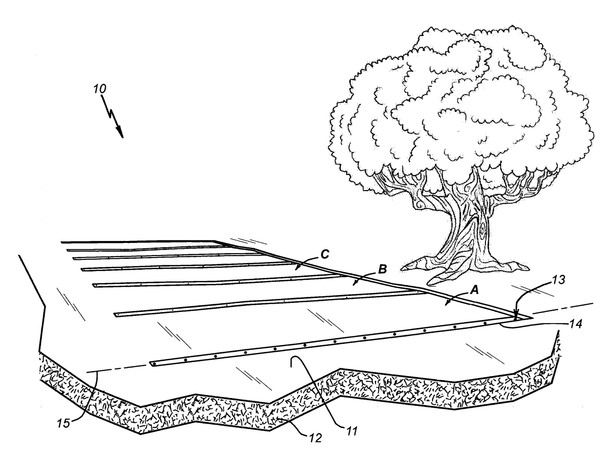
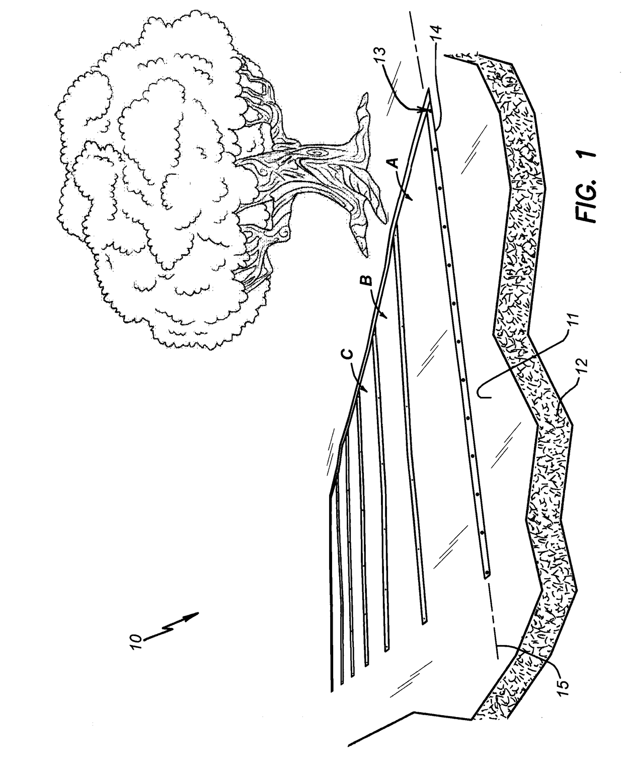
[0017]A parking lot installation constructed according to the present invention is identified in FIG. 1 of the drawings as a parking lot installation 10. It has been constructed in line with the methodology of the present invention on an upwardly facing surface 11 of an underlying body of material 12 in order to delineate multiple parking stalls 13 on the surface 11 at which people can park their vehicles (not shown). Just three of the six parking stalls in FIG. 1 are identified with reference letters for illustrative purposes (i.e., parking stalls A, B, and C). The other three parking stalls are similar to the nine-foot by eighteen-foot parking stalls A, B, and C.

[0018]Although the illustrated surface 11 in FIG. 1 is unpaved (e.g., dirt or grass), and the underlying body of material 12 is dirt (i.e., soil, earth, ground, terra firma), an installation may be constructed according to the present invention on concrete, blacktop, or other underlying body instead of dirt. In addition, the


PUM


Abstract

A method for delineating parking stalls on a parking lot surface includes providing lengths of webbing and a plurality of stake assemblies. The method proceeds by arranging the lengths of webbing in a desired pattern on the parking lot surface that delineates parking stalls, preferably stretching them lengthwise, and then driving stake assemblies through holes in the webbing and into the underlying body of material in order to secure the webbing on the parking lot surface. A parking lot installation constructed according to the invention includes a plurality of lengths of webbing that have been arranged and secured as stated above. The method is not limited to parking lots and parking stall delineation, as it can be used to mark a boundary or delineate a space for other purposes.

Description


Claims


Application Information

Patent Timeline
Owner RAMIREZ MARCOS MARTIN
Why Eureka
Try Eureka