Element and electric generator
- Summary
- Abstract
- Description
- Claims
- Application Information
AI Technical Summary
Benefits of technology
Problems solved by technology
Method used
Image

Examples
example 1
[0196]
[0197]—Production of Intermediate Layer—
[0198]Silicone rubber (IVS4312, manufactured by Momentive Performance Materials Inc.) was applied onto a polyethylene terephthalate (PET) film, and the applied silicone rubber composition was heated to cure at 120° C. for 30 minutes, to thereby form a thin film having a thickness of 100 μm.
[0199]Subsequently, the thin film was subjected to a corona discharge treatment under the following conditions. Thereafter, the PET film was peeled. In the manner as described above, an intermediate layer was obtained.
[0200]
[0201]Applied voltage: 100 V
[0202]Cumulative energy: 60 J / cm2
[0203]Reaction atmosphere: air
[0204]—First Electrode and Second Electrode—
[0205]As for each of a first electrode and a second electrode, AL-PET 9-100 (thickness of aluminium foil: 9 μm, thickness of polyethylene terephthalate film: 100 μm (cover material)) manufactured by PANAC CO., LTD. was provided.
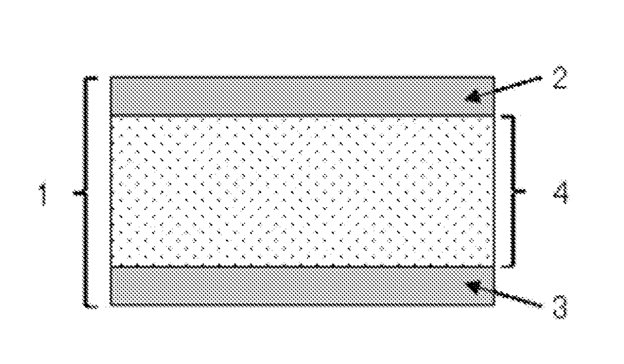
[0206]—Production of Element—
[0207]The obtained intermediate layer was sa
example 2
[0222]
[0223]—Production of Intermediate Layer—
Silicone rubber (KE-1935, manufactured by Shin-Etsu Chemical Co., Ltd.) was applied onto a polyethylene terephthalate (PET) film, and the applied silicone rubber composition was heated to cure at 120° C. for 30 minutes, to thereby form a thin film having a thickness of 100 μm.
Subsequently, the thin film was subjected to a corona discharge treatment in the same manner as in Example 1. Then, the PET film was peeled to thereby produce an intermediate layer of Example 2.
[0224]—Productions of Element and Electric Generator—
[0225]An element and an electric generator of Example 2 were produced using the produced intermediate layer in the same manner as in Example 1.
[0226]
[0227]>
[0228]The produced intermediate layer of Example 2 was subjected to a measurement of an infrared absorption spectrum in the same manner as in Example 1. As a result, the variation rate of the peak intensity ratio was 0.80. It was confirmed from the obtained variation rate t
example 3
[0231]
[0232]—Production of Intermediate Layer—
[0233]A silicone rubber composition was prepared by dispersing 100 parts by mass of silicone rubber (IVS4312, manufactured by Momentive Performance Materials Inc.), 50 parts by mass of barium titanate (208108, manufactured by Sigma-Aldrich Co., LLC.).
[0234]Subsequently, the silicone rubber composition was applied onto a polyethylene terephthalate (PET) film, and the applied silicone rubber composition was heated to cure at 120° C. for 30 minutes, to thereby form a thin film having a thickness of 100 μm.
[0235]Subsequently, the thin film was subjected to a corona discharge treatment in the same manner as in Example 1. Then, the PET film was peeled to thereby produce an intermediate layer of Example 3.
[0236]—Productions of Element and Electric Generator—
[0237]An element and an electric generator of Example 3 were produced using the produced intermediate layer in the same manner as in Example 1.
[0238]
[0239]>
[0240]The produced intermediate layer
PUM
| Property | Measurement | Unit |
|---|---|---|
| Length | aaaaa | aaaaa |
| Fraction | aaaaa | aaaaa |
| Fraction | aaaaa | aaaaa |
Abstract
Description
Claims
Application Information
 - R&D Engineer
- R&D Manager
- IP Professional
- Industry Leading Data Capabilities
- Powerful AI technology
- Patent DNA Extraction
Browse by: Latest US Patents, China's latest patents, Technical Efficacy Thesaurus, Application Domain, Technology Topic.
© 2024 PatSnap. All rights reserved.Legal|Privacy policy|Modern Slavery Act Transparency Statement|Sitemap