Method for producing a water-tight plug connector

a plug connector and watertight technology, applied in the direction of couplings/cases, line/current collector details, coupling device connections, etc., can solve the problems of negative effects on the electrical and mechanical properties of the plug connector and the transmission of signals

Active Publication Date: 2018-03-29
ROSENBERGER HOCHFREQUENZTECHNIK GMBH & CO KG
View PDF2 Cites 3 Cited by
  • Summary
  • Abstract
  • Description
  • Claims
  • Application Information

AI Technical Summary

Benefits of technology

The present invention relates to an insulating material used in a water-tight plug connection between two parts. This material has a guide channel where it holds the conductive wire before filling the space inside the plug connector housing. When this material is cast into the plug connector housing, there are openings on both ends of the housing. These openings can be covered by a covering when they are closed after filling them.

Problems solved by technology

The technical problem addressed in this patent text is how to improve the stability and durability of plug connectors while also reducing the risk of damaging their components when they leak liquid during use.

Method used


Image

  • Method for producing a water-tight plug connector
  • Method for producing a water-tight plug connector
  • Method for producing a water-tight plug connector

Examples


Embodiment Construction

)

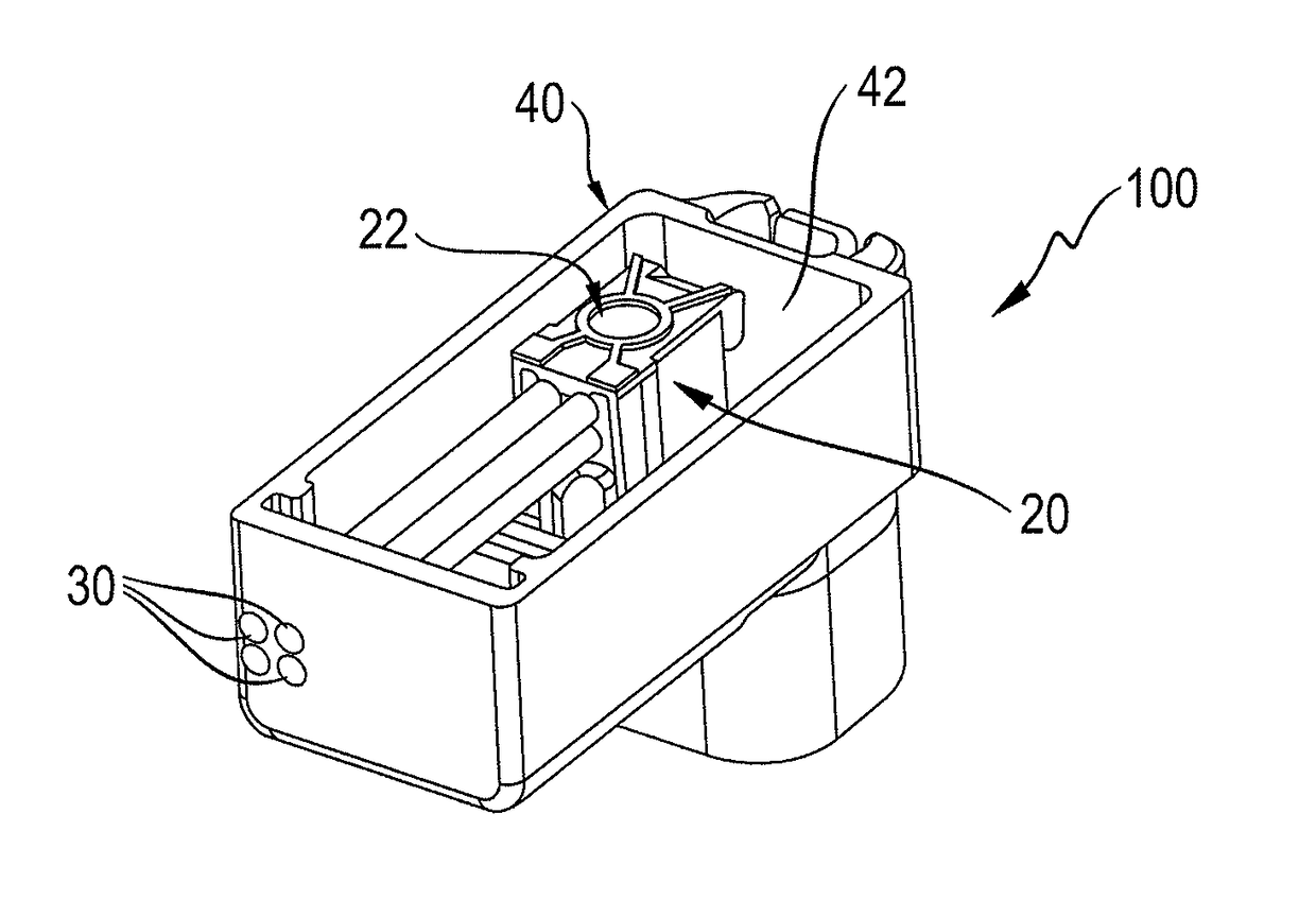
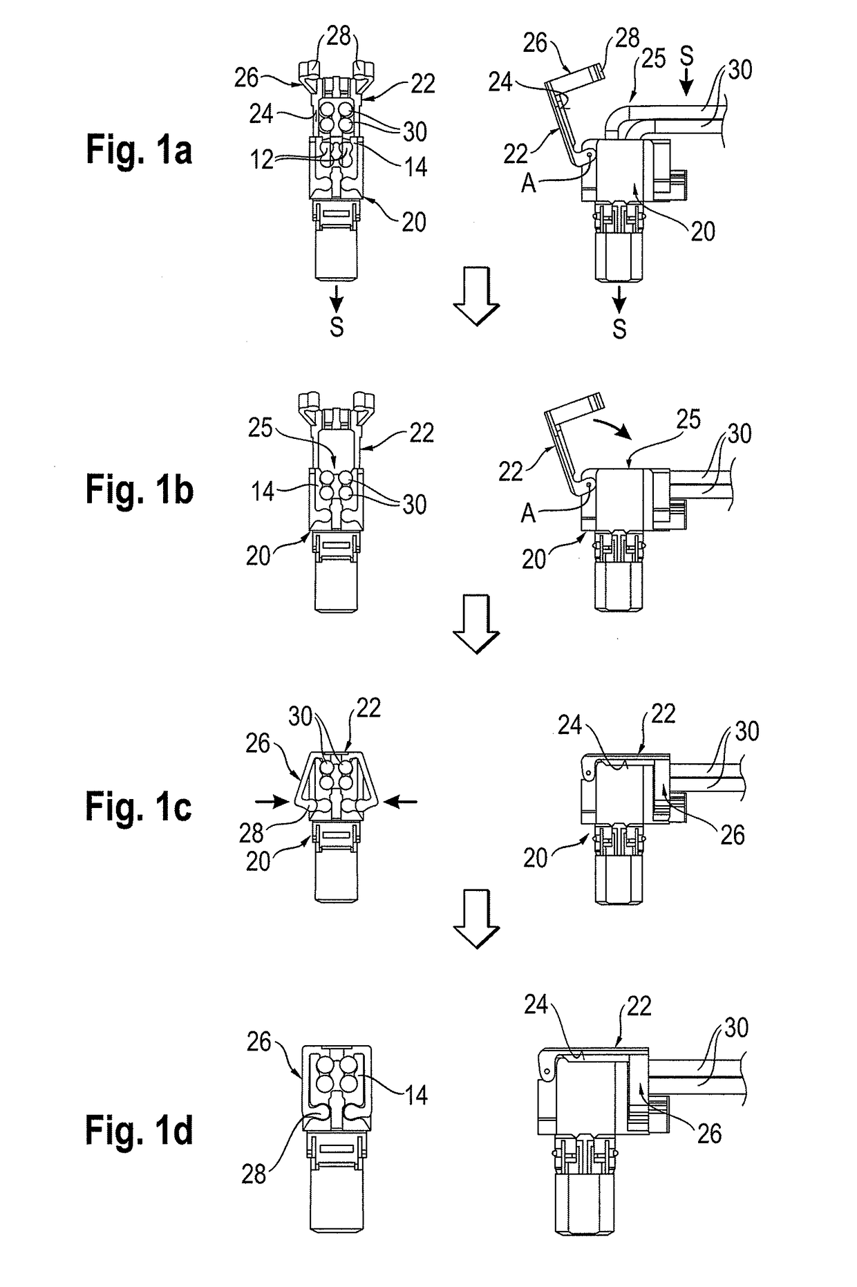
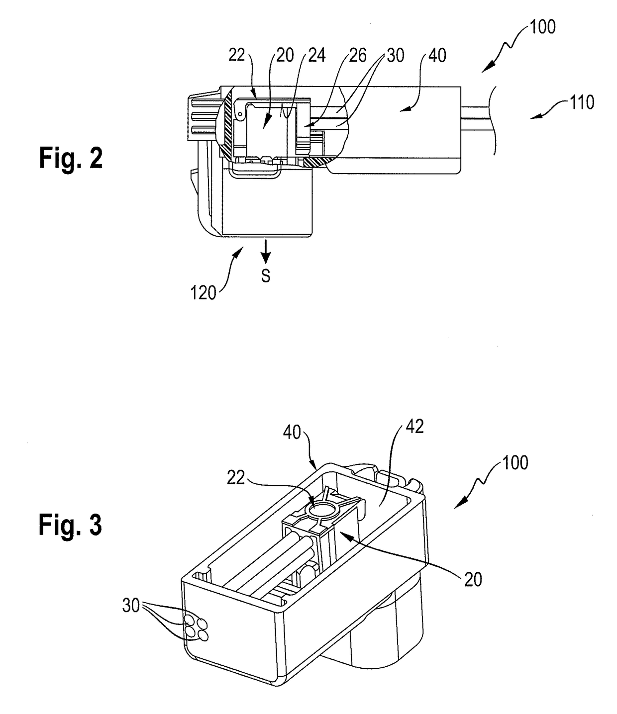
[0020]In describing the preferred embodiment of the present invention, reference will be made herein to FIGS. 1-3 of the drawings in which like numerals refer to like features of the invention.

[0021]The invention is based on the knowledge that, after a conductor has been introduced into the guide channel of the insulator part via a lateral opening, a paste-like or viscous sealing compound can, during filling, penetrate through the open lateral opening into the interior of the insulator part, as far as the guide channel, as a result of which the course of the conductor in the guide channel can be changed.

[0022]For example, the sealing compound which has penetrated into the guide channel undergoes a change in volume during the hardening process, as a result of which the conductor can be pressed mechanically against a wall of the guide channel or against the adjacent conductor. A change of the dielectric between several conductors and / or a change in the spacing between them through the


PUM


Abstract

A method for producing a water-tight plug connector in which at least one electric conductor such as a wire is introduced into a guide channel of an insulator part via a lateral opening in order to hold the conductor. The insulator part with the introduced conductor is arranged in a plug connector housing, and the lateral opening of the insulator part is closed by a cover. An internal volume of the plug connector housing is then at least partly filled with a sealing compound. A plug connector is produced in such a manner.

Description


Claims


Application Information

Patent Timeline
Owner ROSENBERGER HOCHFREQUENZTECHNIK GMBH & CO KG
Why Eureka
Try Eureka