Coil module and wireless power transmission device using the same

a technology of coil module and wireless power transmission device, which is applied in the directions of transformer/inductance magnetic core, core/yoke, transportation and packaging, etc., can solve the problem of limiting the number of coil modules that need to be configured separately for each coil

Active Publication Date: 2018-09-06
WITS CO LTD
View PDF0 Cites 5 Cited by
  • Summary
  • Abstract
  • Description
  • Claims
  • Application Information

AI Technical Summary

Benefits of technology

The present inventor describes an improved design for wirelessly transmitting electrical energy from one unit (the transmitter) through another unit called the receiver's antenna. This allows more efficient use of space while still maintaining good performance compared to previous designs.

Problems solved by technology

The technical problem addressed in this patented text relates how efficient charging can occur when multiple electrical components (such as batteries) share their same space without generating too much heat or causing interference issues due to mutual proximity.

Method used


Image

  • Coil module and wireless power transmission device using the same
  • Coil module and wireless power transmission device using the same
  • Coil module and wireless power transmission device using the same

Examples


Embodiment Construction

[0044]The following detailed description is provided to assist the reader in gaining a comprehensive understanding of the methods, apparatuses, and / or systems described herein. However, various changes, modifications, and equivalents of the methods, apparatuses, and / or systems described herein will be apparent after an understanding of the disclosure of this application. For example, the sequences of operations described herein are merely examples, and are not limited to those set forth herein, but may be changed as will be apparent after an understanding of the disclosure of this application, with the exception of operations necessarily occurring in a certain order. Also, descriptions of features that are known in the art may be omitted for increased clarity and conciseness.

[0045]The features described herein may be embodied in different forms, and are not to be construed as being limited to the examples described herein. Rather, the examples described herein have been provided me


PUM


Abstract

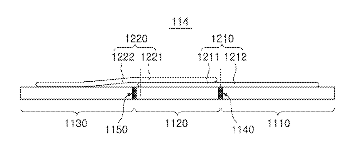
A coil module includes a magnetic substance plate, a first coil, and a second coil. The magnetic substance plate includes a first area having a first magnetic permeability and a second area having a second magnetic permeability. The first coil is disposed on a surface of the magnetic substance plate. The second coil is disposed on the surface of the magnetic substance plate and partially overlapping the first coil. A portion of the first coil, not overlapping the second coil, is disposed on a surface of the first area, and a portion of the second coil, not overlapping the first coil, is disposed on a surface of the second area.

Description


Claims


Application Information

Patent Timeline
Owner WITS CO LTD
Why Eureka
Try Eureka