Divided flow guiding device, kit comprising base body and end piece of a flow guiding device, filter unit and method for cleaning

a flow guiding device and flow guiding technology, which is applied in the field of filter cartridges, can solve the problems of incomplete flow guiding device portion of filter cartridges, and achieve the effects of reducing the distance between the nozzle and the filter cartridge, improving the cleaning result, and optimizing the cleaning resul

Active Publication Date: 2019-08-15
CAMFIL APC GMBH
View PDF0 Cites 6 Cited by
  • Summary
  • Abstract
  • Description
  • Claims
  • Application Information

AI Technical Summary

Benefits of technology

The present invention relates to a filter unit used in filters for cleaning contaminated gases. It achieves this by arranging multiple filter elements together along their own axis instead of just one single element. These filter elements have different parts attached to them, such as a compressor tank containing a nozzle and a filter material. When compressed air flows through these components, the compressed air flow expands outward beyond its original position, causing the filter material to become wider towards the center of the component. This allows more space around the filter element without being obstructed or reducing the overall dimensions of the filter unit. Additionally, the use of a narrower nozzle reduces energy lost during the cleaning process compared to traditional methods where the nozzles are placed closer to the filter material. Overall, this design improves efficiency and performance of the filter unit while maintaining minimal energy usage.

Problems solved by technology

The filter element in existing technology needs to be replaced regularly, resulting in the production of a new flow guide device every time the filter element is replaced. Even if the service life of the flow guide device is longer than the filter element, it still needs to be replaced. This resulted in incomplete flow guide components of the filter element. In other words, at least a portion of the flow guide device, i.e. the end piece, is not fixed to the filter material and/or filter element. In addition, when the filter element is formed from the filter element material, the flow of contaminated gas enters the internal area through the filter element, especially through the filter element material.

Method used


Image

  • Divided flow guiding device, kit comprising base body and end piece of a flow guiding device, filter unit and method for cleaning
  • Divided flow guiding device, kit comprising base body and end piece of a flow guiding device, filter unit and method for cleaning
  • Divided flow guiding device, kit comprising base body and end piece of a flow guiding device, filter unit and method for cleaning

Examples


Embodiment Construction

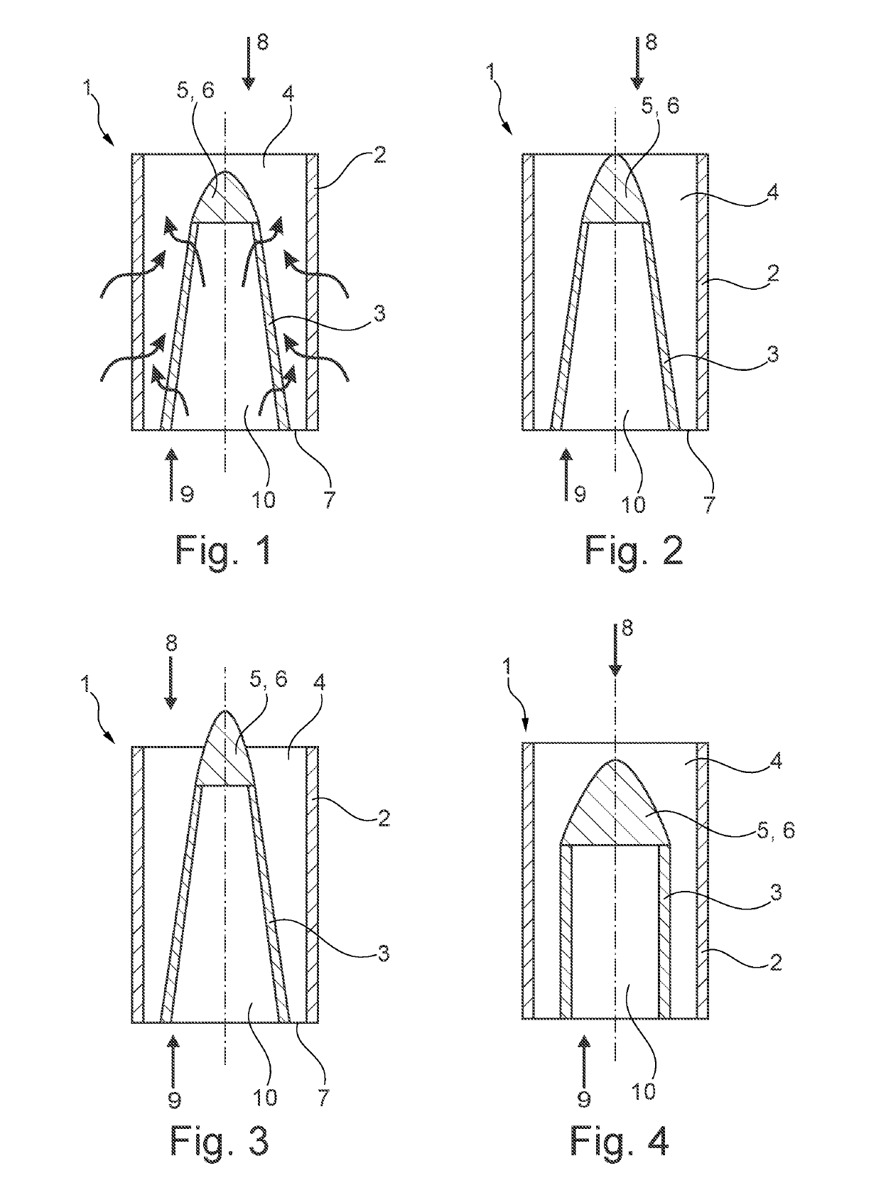
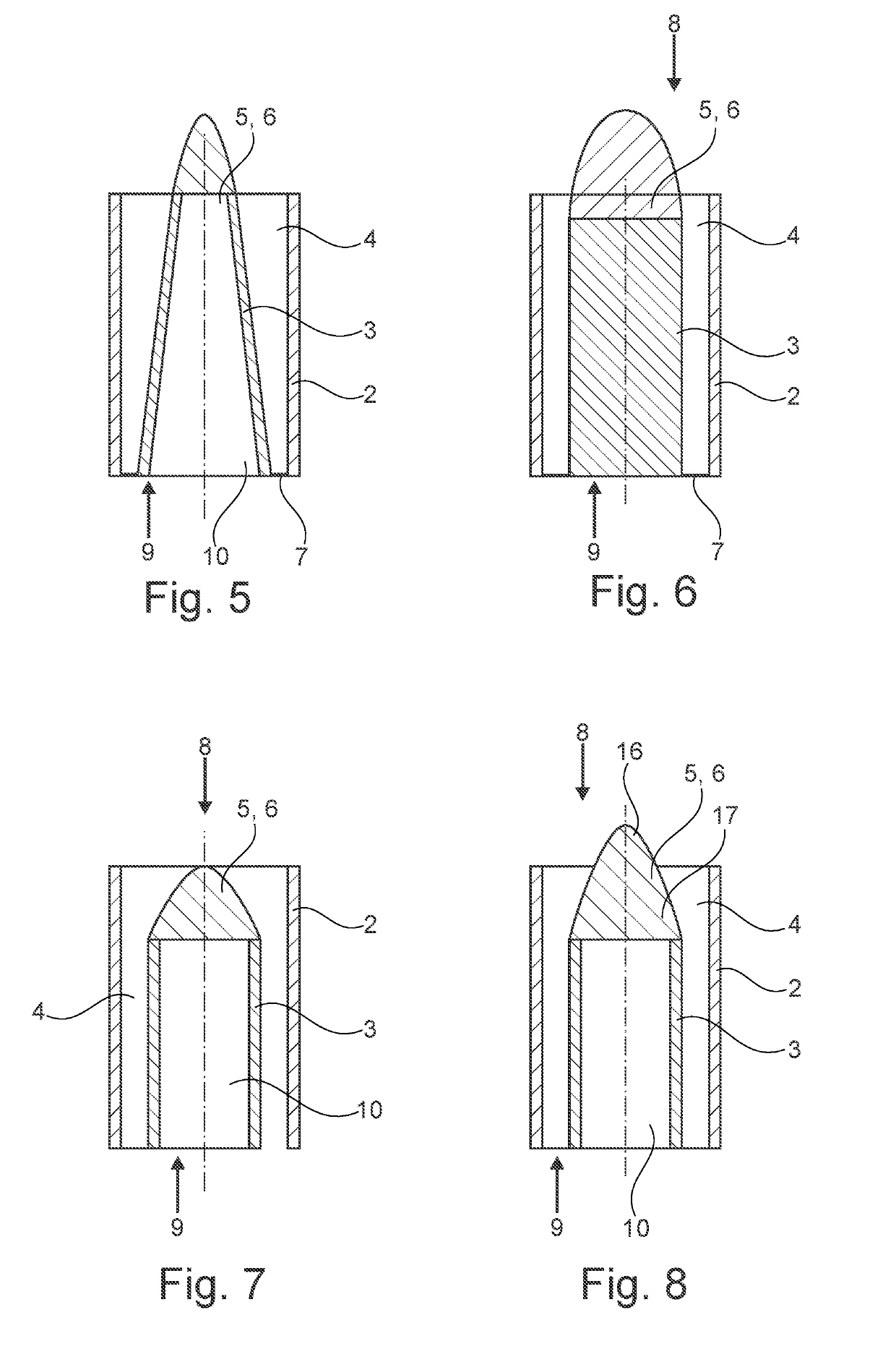
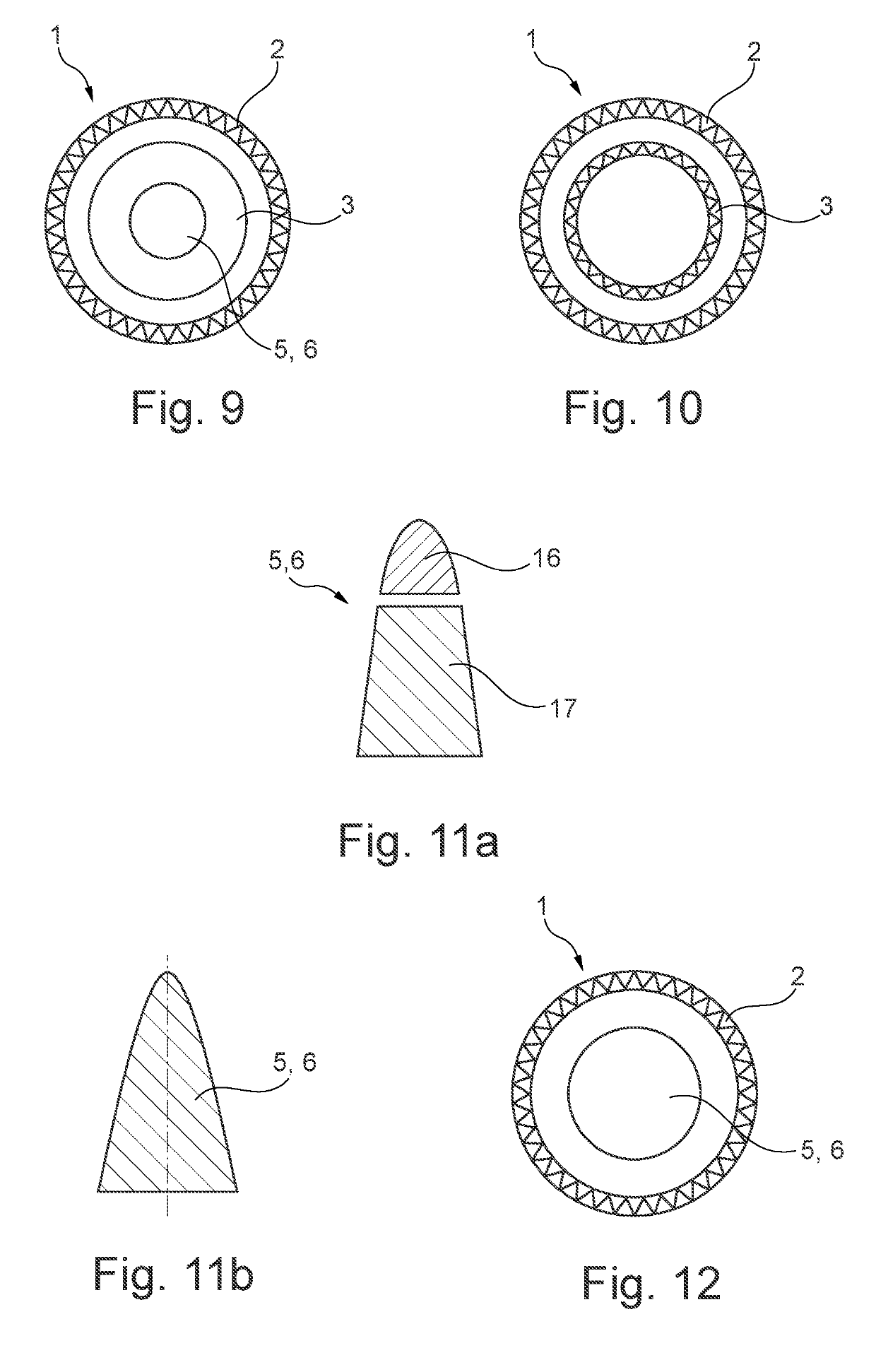
[0105]FIG. 1 illustrates a filter cartridge 1 for removing impurities from a dirty gas flow to be filtered. The filter cartridge 1 includes a cylindrical filter element 2, also referred to as an outer pack, with the filter element 2 being made from filter material. In the cylindrical filter element 2 a filter insert 3 is inserted. The filter insert 3 is also referred to as an inner pack. The filter insert 3 is made from filter material. The filter element 2 and the filter insert 3 are arranged coaxially to each other. Within the filter cartridge 1 thus an inner space 4 is formed which is ring-shaped in the area between the filter element 2 and the filter insert 3. The filter material of the filter element 2 and of the filter insert 3 is designed so that it is cleaned when compressed air flow which flows against a flow direction of the dirty gas flow is applied. The filter cartridge 1 includes a cap 6 in the form of a flow guiding device 5 which is disposed and designed with respect to


PUM

PropertyMeasurementUnit
Fractionaaaaaaaaaa
Flow rateaaaaaaaaaa
Diameteraaaaaaaaaa

Abstract

The present application relates to a filter cartridge for removing impurities from a dirty gas flow to be filtered, including a cylindrical filter element made from filter material, a filter insert inserted in the filter element, an inner space formed between the filter element and the filter insert, with the filter material being designed for being cleaned when a compressed air flow is applied against a flow direction of the dirty gas flow, and a base body of a flow guiding device having a surface designed for guiding the compressed air flow, wherein the base body has a distal end zone which is prepared for being completed by an end piece separate from the filter cartridge and mountable to an external housing for flow guiding the compressed air flow. Further, the present application relates to a kit, a filter unit, and a method for cleaning the filter cartridge.

Description


Claims


Application Information

Patent Timeline
Owner CAMFIL APC GMBH
Why Eureka
Try Eureka