A structural element
a structural element and steel technology, applied in the direction of towers, buildings, bulkheads/piles, etc., can solve the problems of weakening the structure, not easy to attach other people, and difficult to control and consistently maintain the quality of steel bindings
- Summary
- Abstract
- Description
- Claims
- Application Information
AI Technical Summary
Benefits of technology
Problems solved by technology
Method used
Image

Examples
first embodiment
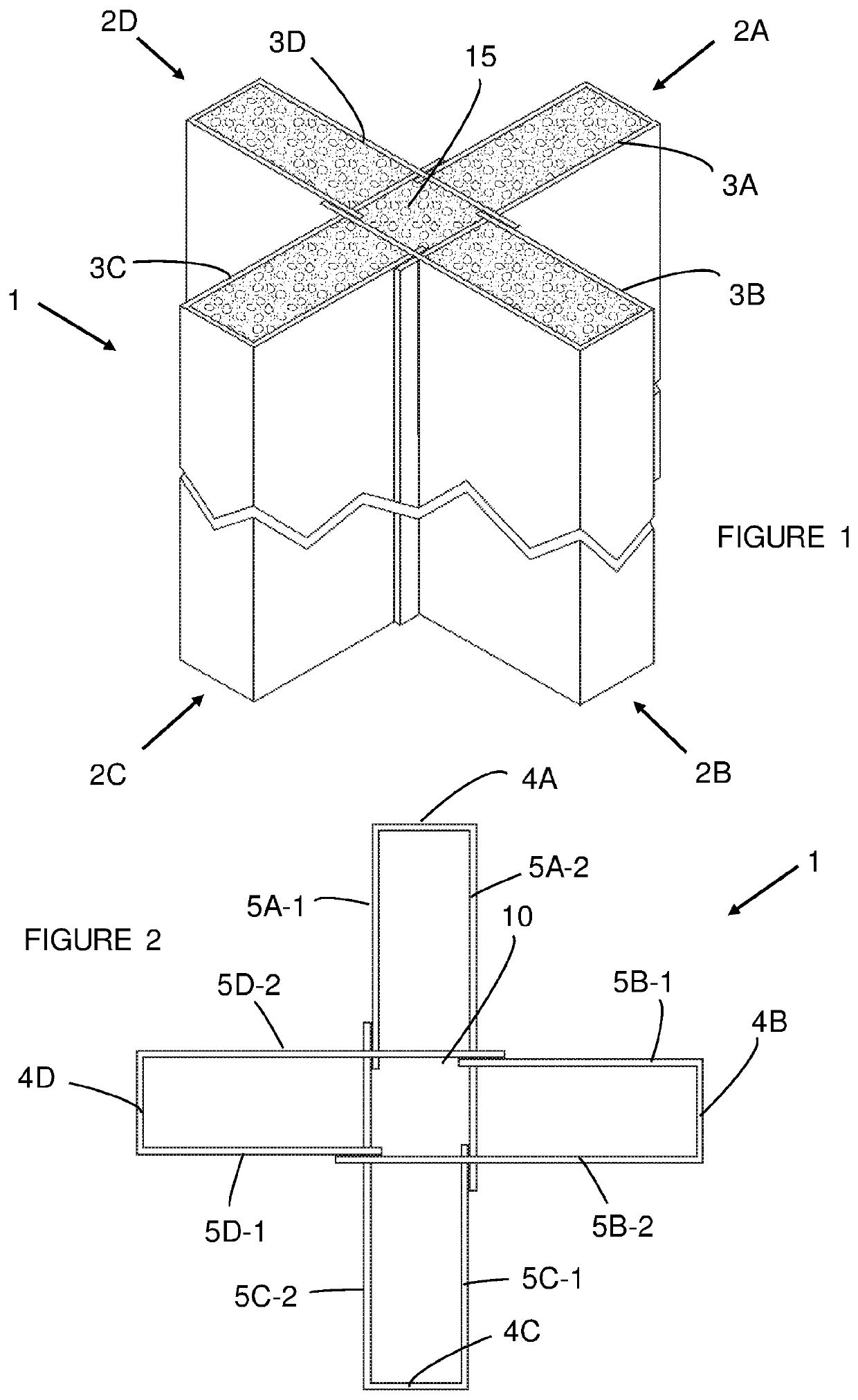
[0052]the structural element (1), as shown in detail in FIGS. 1 and 2, is comprised of a plurality of interlocked resilient sheet material components (2A-D). Each component is formed from a sheet (3A-D) by being shaped to provide an elongate base (4A-D) with two opposing edges from which a first extension (5A-1, 5B-1, 5C-1, 5D-1) and a second extension (6A-2, 6B-2, 6C-2, 6D-2) respectively extend, with the respective second extension (6A-2, 6B-2, 6C-2, 6D-2) extending further from the respective base (4A-D) than the respective first extension (5A-1, 5B-1, 5C-1, 5D-1).
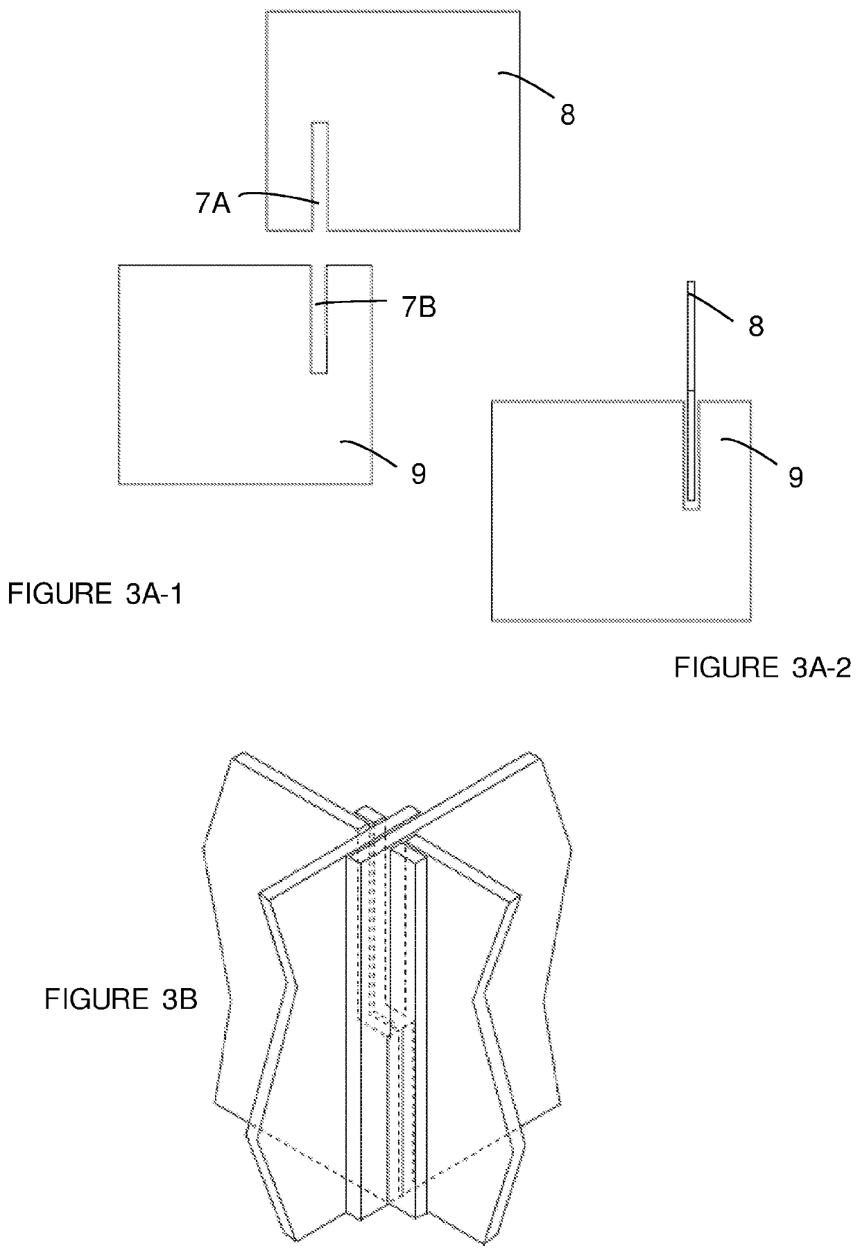
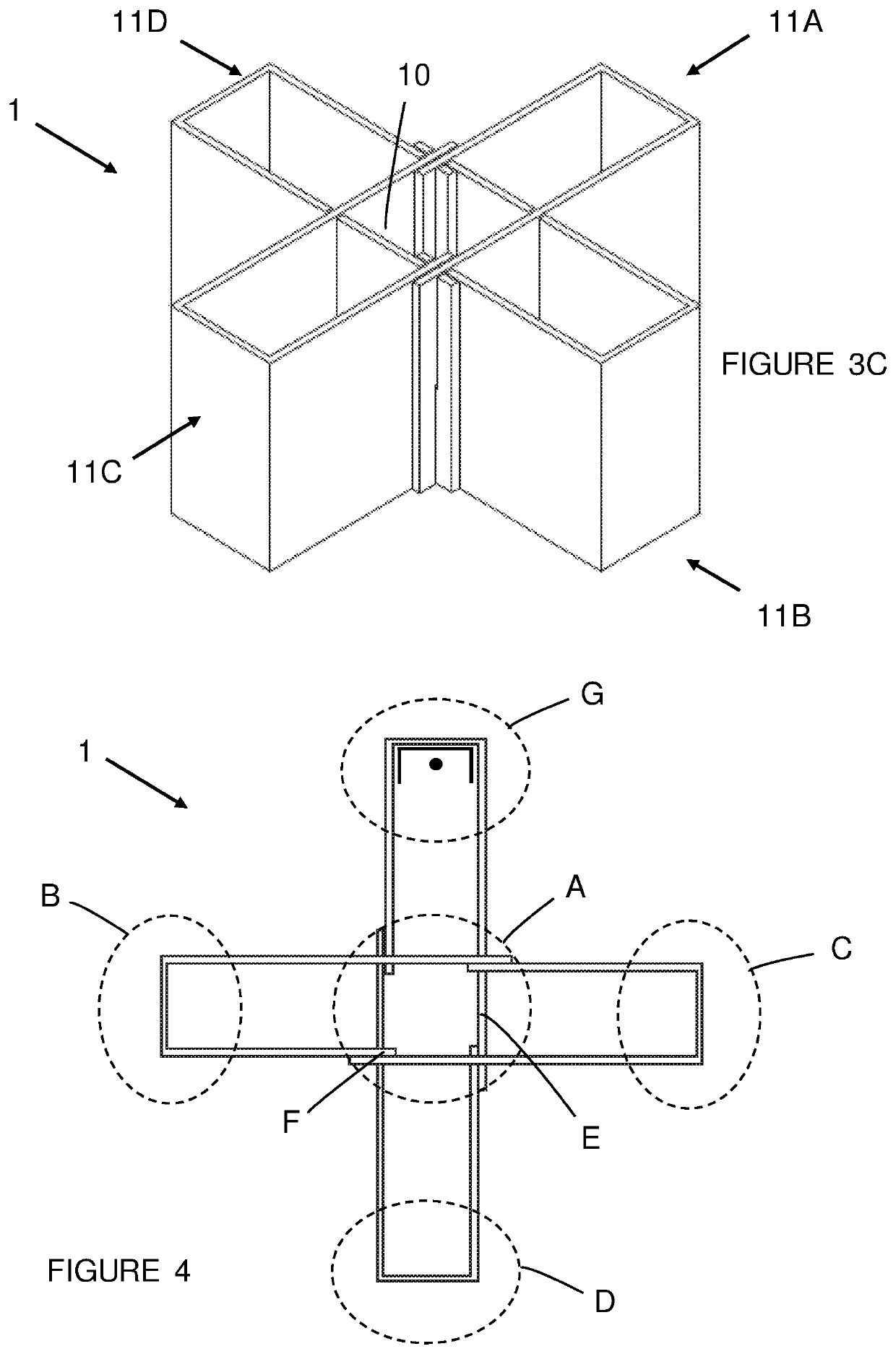
[0053]As shown in FIG. 3 the first (5A-1, 5B-1, 5C-1, 5D-1) and second (6A-2, 6B-2, 6C-2, 6D-2) extensions are provided with complimentary interlocking means, in this embodiment in the form of slots (7). As shown in FIG. 3A, this enables the extensions of one sheet material component (8) to be interlocked with the extensions of another sheet material component (9).
[0054]In the structural element the extensions of four shee
second embodiment
[0079]a structural element (30) according to the invention is shown in FIGS. 10-14. In this instance the structural element (30) is comprised of four sheet components, each of which includes first (31) and the second (32) extensions that extend from a base (33). Each of the first (31) and the second (32) extensions terminate in an edge that is provided with a series of spaced apart tabs (34, 35) and slots (36, 37).
[0080]The tabs (34) of each first extension (31) are located longitudinally opposite the slots (37) of its second extension (32) and the tabs (35) of its second extension (32) are located longitudinally opposite the slots (36) of its first extension (31). The tabs (35) of the second extension (32) are longer than the tabs (34) of the first extension (31), which enables in respect of each sheet component (30) the second extension (32) to extend further from the base (33) than its first extension (31).
[0081]As shown in FIGS. 10 and 11 the bases (33) of the components may have c
PUM
 Abstract
Description
Claims
Application Information
 - R&D Engineer
- R&D Manager
- IP Professional
- Industry Leading Data Capabilities
- Powerful AI technology
- Patent DNA Extraction
Browse by: Latest US Patents, China's latest patents, Technical Efficacy Thesaurus, Application Domain, Technology Topic.
© 2024 PatSnap. All rights reserved.Legal|Privacy policy|Modern Slavery Act Transparency Statement|Sitemap