Medical Device, Method and Systems

a medical device and system technology, applied in the field of medical devices, can solve the problems of difficult patient maintenance of desired schedule, high malfunction rate, and many potentially valuable medicines or compounds, including biologicals, and achieve the effect of improving the safety and safety of patients

Pending Publication Date: 2021-03-11
DEKA PROD LLP
View PDF2 Cites 2 Cited by
  • Summary
  • Abstract
  • Description
  • Claims
  • Application Information

AI Technical Summary

Benefits of technology

This invention relates to systems for wirelessly supplying power (charges) to electronic devices such as blood glucose monitors used by patients with diabetics. These systems use wireless technology to charge batteries inside them while they are being worn on their body over time. Users can also connect these battery-powered sensors directly into their healthcare settings through specialized connections like cables. They have buttons/buttons where users input data about themselves' activities during testing periodically. There will likely exist multiple types of alarms depending upon how well certain measurements were taken compared against each other.

Problems solved by technology

This patented technical solution described in the text relates to improving the effectiveness of injector therapy through improved control over dosage timing and ease of use during treatment sessions. However, current methods require multiple steps involving complicated equipment like pumps, tubes, valves, etc., making them challenging to manufacturers who want more affordability at home. There needs improvement in terms of reducing complexity and costs associated with existing solutions without compromising their efficacy.

Method used


Image

  • Medical Device, Method and Systems
  • Medical Device, Method and Systems
  • Medical Device, Method and Systems

Examples


Embodiment Construction

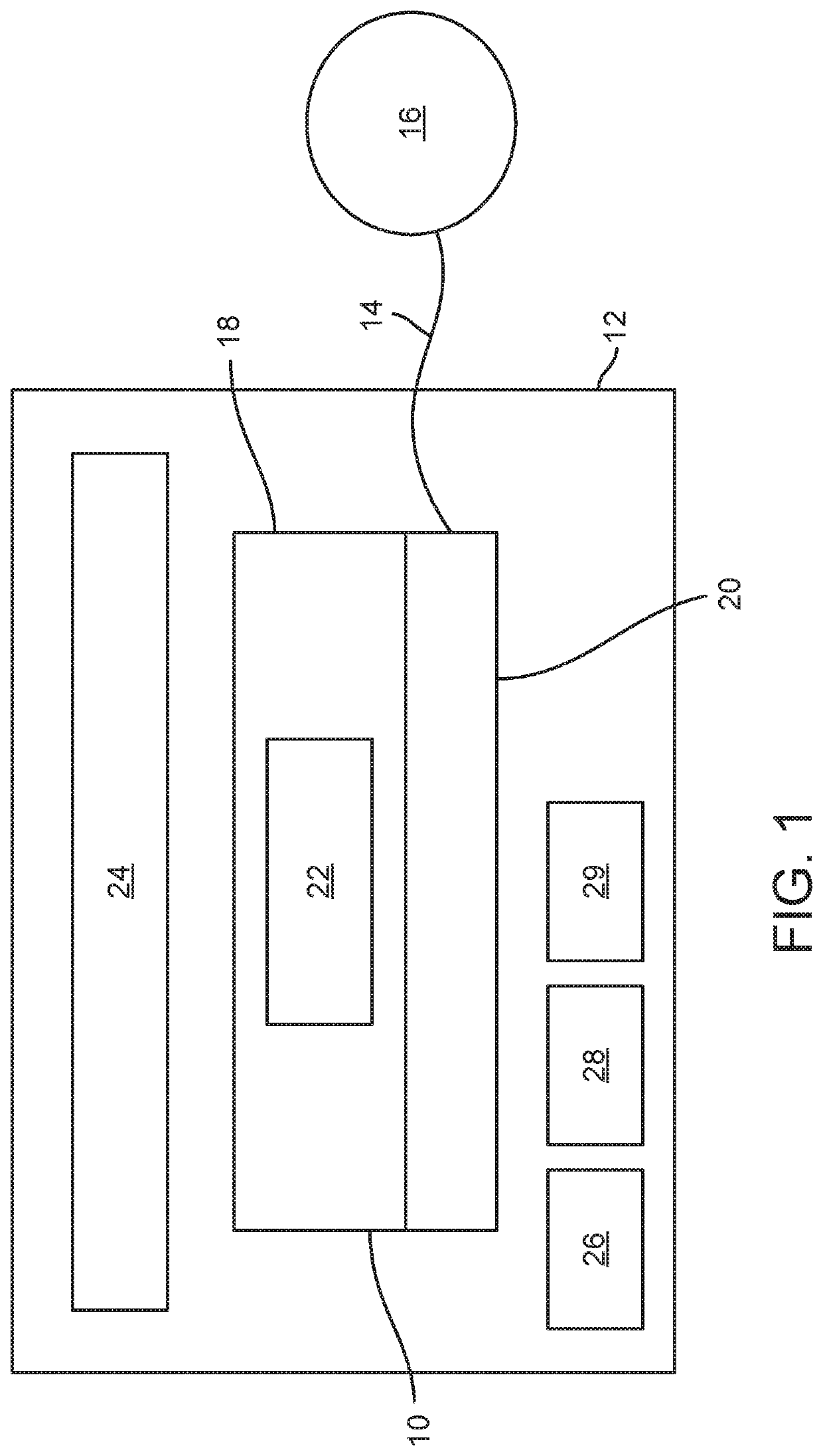
[0036]FIG. 1 depicts a block diagram of a medical device 10 and coupled accessory 12. The medical device 10 may be any medical device including, but not limited to, ambulatory medical devices, drug delivery devices, physiological monitors, analyte sensors, diabetes management devices, and medical devices intended for use in a home or other non-clinical / non-hospital setting. A single accessory 12 may also be coupled to multiple medical devices 10 (e.g. an insulin pump and glucose meter). The block diagram shown in FIG. 1 depicts the medical device 10 as a drug delivery device which is in fluid communication via tubing 14 with a patient access 16 such as, for example, a needle, cannula, or subcutaneous infusion set. The medical device 10 may deliver a drug or drugs such as insulin, glucagon, treprostinil, an oncology drug, etc., or some combination thereof to the patient.

[0037]The medical device 10 is depicted as having a first portion 18 and second portion 20. The second portion 20 ma


PUM


Abstract

A medical device system is disclosed. The medical system includes a medical device including a first portion and a second portion; and an accessory, wherein the accessory configured to attach to the medical device and provide battery power to the medical device.

Description


Claims


Application Information

Patent Timeline
Owner DEKA PROD LLP
Why Eureka
Try Eureka