Gulf Current Electric Generator

a current electric generator and gulf current technology, applied in the direction of machines/engines, mechanical energy handling, mechanical equipment, etc., can solve the problems of not being efficient enough to create and maintain these devices, and not being able to create and maintain them

Inactive Publication Date: 2021-04-01
DERAN BARRY
View PDF0 Cites 0 Cited by
  • Summary
  • Abstract
  • Description
  • Claims
  • Application Information

AI Technical Summary

Benefits of technology

This patented design allows for easy use with a gulf current electric generator that uses two different types of cathodes. One type is called a small spiral tube made up of tiny propellers attached to a narrow end. Another type is called a large spiral tube made up of many propellers arranged around it. These cathode arrangements are designed to work together efficiently.

Problems solved by technology

This patent describes a technical problem with generating electrical power by utilizing sea water movements or other sources of energy on the surface of the earth. Current methods involve converting them into more useful forms such as hydroelectricity or wind-power, but their efficiency has proven insufficient due to factors like wave action and tidal movement. Therefore, the goal of the invention is to improve the efficiency of generating electrical power through improved designs.

Method used


Image

  • Gulf Current Electric Generator
  • Gulf Current Electric Generator
  • Gulf Current Electric Generator

Examples


Embodiment Construction

[0023]Reference is made herein to the attached drawings. Like reference numerals are used throughout the drawings to depict like or similar elements of the gulf current electric generator. For the purposes of presenting a brief and clear description of the present invention, a preferred embodiment will be discussed as used for the gulf current electric generator. The figures are intended for representative purposes only and should not be considered to be limiting in any respect.

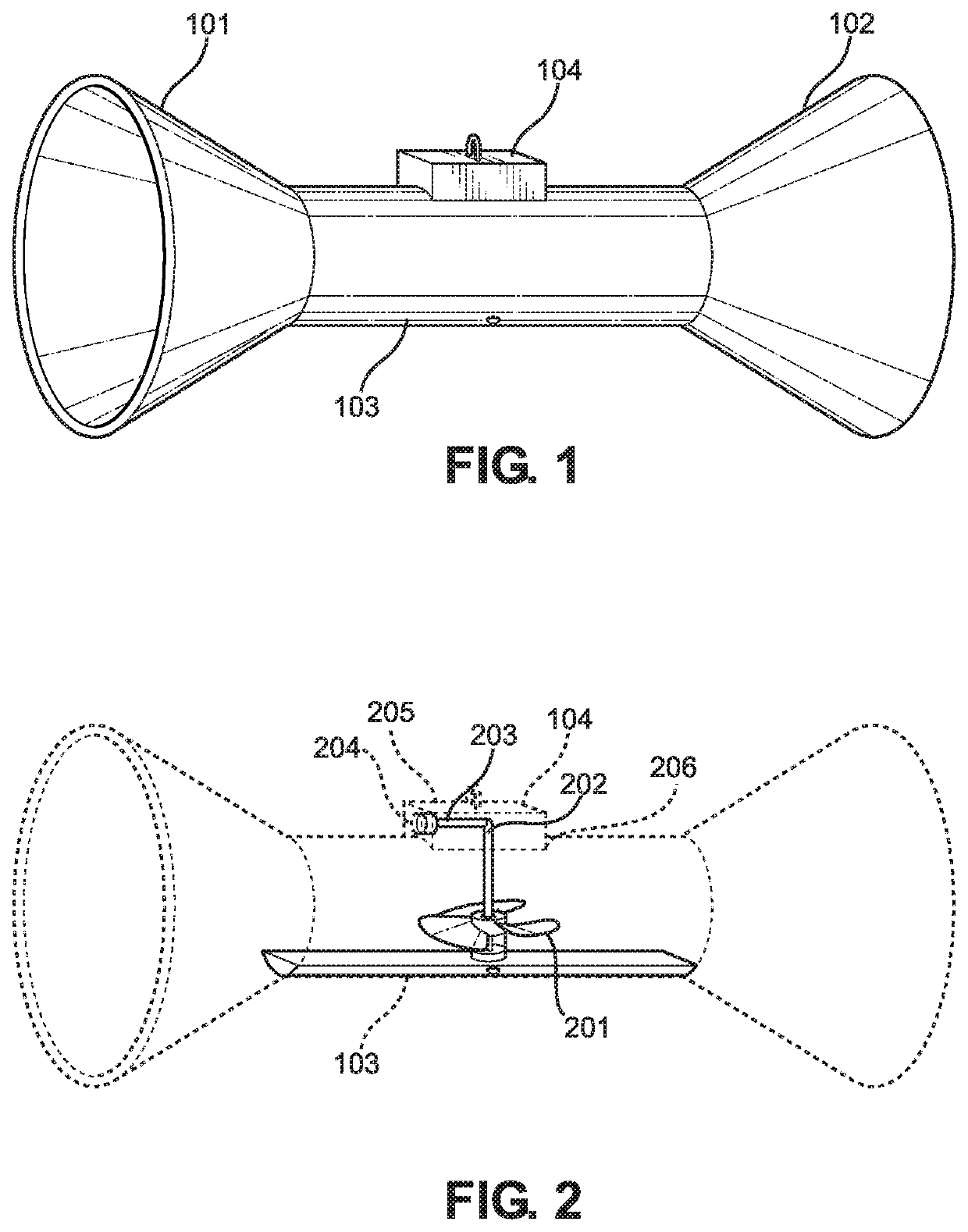
[0024]Referring now to FIG. 1, there is shown a side view of an embodiment of a generator. The gulf current electric generator has a first funnel 101. In one embodiment, the first funnel 101 is conical. In another embodiment, the first funnel is pyramid shaped. In this embodiment there is a rectangular open large end opposite of a rectangular open smaller end with four sidewalls creating the pyramid.

[0025]The gulf current generator has a second funnel 102. In one embodiment, the second funnel 102 is conical. In


PUM


Abstract

A gulf stream electric generator including a first funnel, a second opposite funnel, a propeller, and an electric turbine. The first funnel is a funnel and is placed such that the narrow end connects to an elongated tube. The second funnel is connected to a second end of the elongated tube such that the narrow end is connected to the tube. A propeller is placed within the elongated tube. The propeller is operable coupled to an electric turbine generator. The electric turbine will create an electric charge and send it to a power station for distribution.

Description


Claims


Application Information

Patent Timeline
Owner DERAN BARRY
Why Eureka
Try Eureka