Air-vapor separation device for separating air from refrigerant vapor and method thereof

Active Publication Date: 2021-04-22
DAWNING INFORMATION IND BEIJING
View PDF0 Cites 2 Cited by
  • Summary
  • Abstract
  • Description
  • Claims
  • Application Information

AI Technical Summary

Benefits of technology

[0020]The air-vapor separation device according to the present invention has the advantages of simple structure, convenient operation, and is reliable and effective in separation of air and refrigerant vapor, with good separation effect. The air-vapor separation device and the method thereof according to the present invention, the air may be automatically separated from the refrigerant vapor without affecting the normal cooling of the liquid-cooling system, so that not only may the original air in the liquid-cooling system pipeline be discharged, but also may the air brought into the liquid-cooling system pipeline when repairing and replacing components be discharged for the recovery of the refrigerant, thereby greatly improving the cooling effect of the liquid-cooling system.

Problems solved by technology

Most of the computers currently used rely on cold air to cool the machine, but in the data center, the air-cooling alone is not enough to meet the heat dissipation requirements for servers with high heat flux density.
It has the disadvantages of complicated heat transmission, contact thermal resistance and convection heat transfer resistance, large sum of thermal resistance, low heat transfer efficiency, large temperature difference between heat sources with high and low temperature during heat transfer, and being carried out by requiring outdoor heat sources with lower temperature to guide the heat transfer.
In addition, the working noise of the pump is generally not obvious, so the overall heat dissipation system is very quiet as compared with the air-cooling system.
And then, since the air cannot be condensed, the cooling efficiency of the liquid-cooling system will be affected.

Method used


Image

  • Air-vapor separation device for separating air from refrigerant vapor and method thereof
  • Air-vapor separation device for separating air from refrigerant vapor and method thereof

Examples


Example

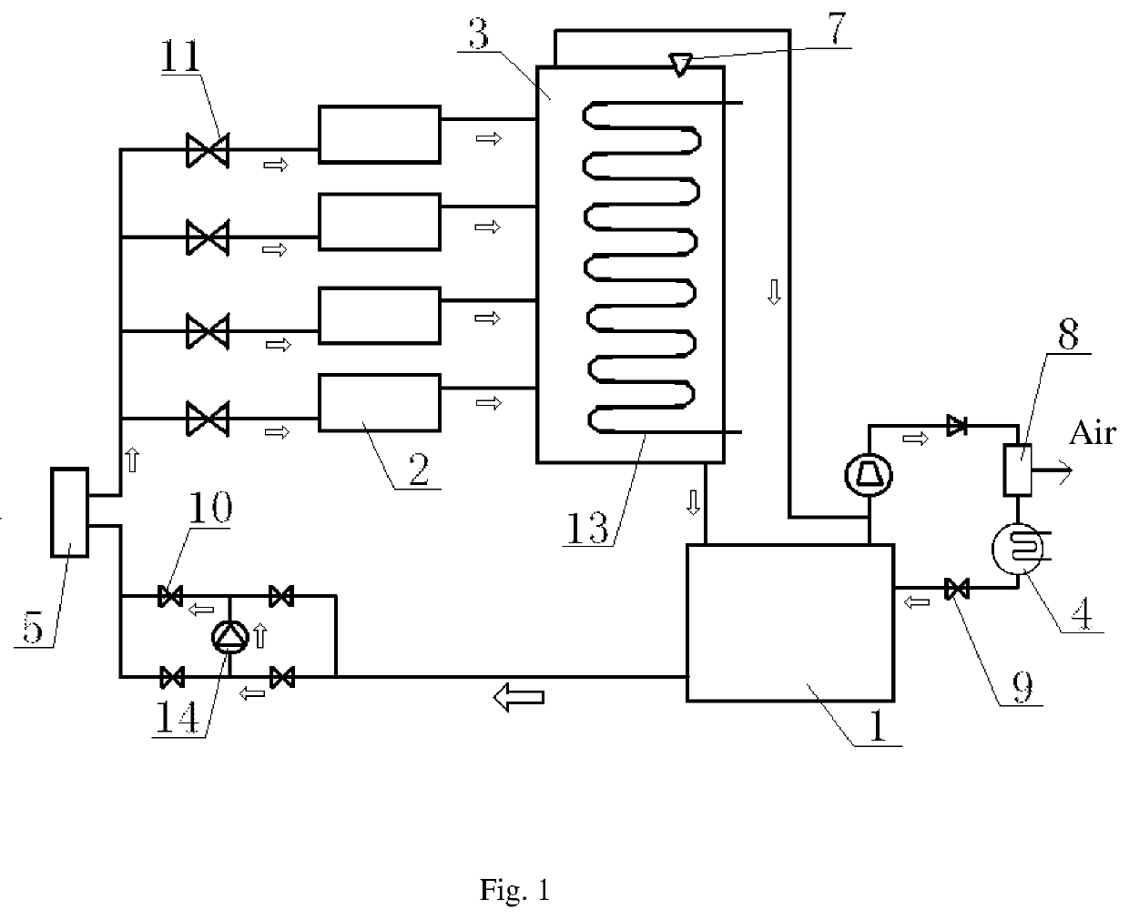
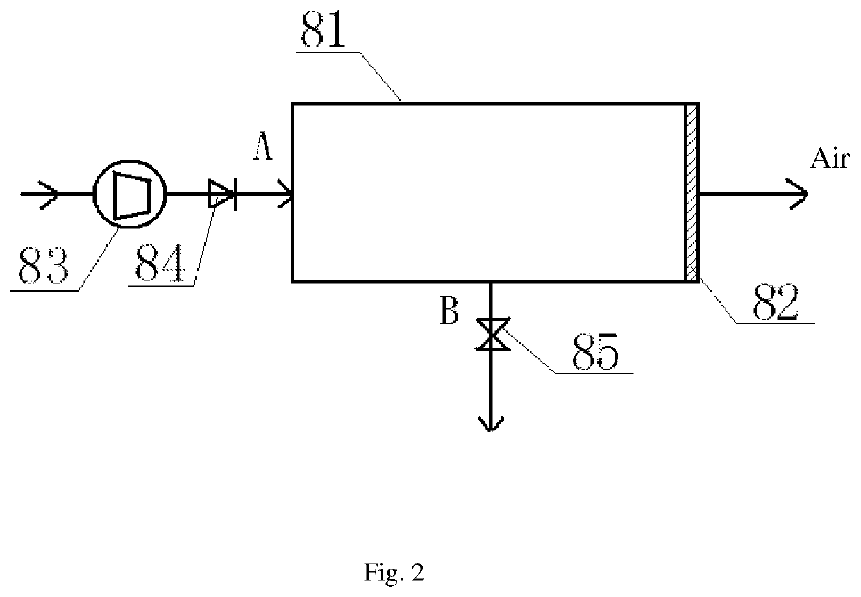
[0023]Description of reference numerals: 1—refrigerant storage tank, 2—immersed blade cabinet, 3—first condenser, 4—second condenser, 5—drying filter, 7—first pressure relief valve, 8—air-vapor separation device, 81—air-vapor separation tank, 82—air-vapor separation membrane, 83—compressor, 84—first control valve, 85—second control valve, 9—first on-off valve, 10—second on-off valve, 11—third on-off valve, 13—condensation coil, 14—refrigerant delivery pump.

DETAILED DESCRIPTION OF THE PREFERRED EXAMPLES

[0024]To make the purpose, technical solutions and advantages of the present invention clearer, the embodiments of the present invention will be described below in detail in combination with the drawings. It should be noted that, in the case of no conflicts, the embodiments in the present invention and features in the embodiments can be combined mutually and arbitrarily.

[0025]According to an embodiment of the present invention, an immersed liquid-cooling system directly immerses a server


PUM


Abstract

The present invention relates to an air-vapor separation device for separating air from refrigerant vapor comprising an air-vapor separation tank, a separation membrane, a mixed gas input passage, a refrigerant vapor output passage, and a control unit, wherein the mixed gas input passage is provided with a compressor and a first control valve, and the refrigerant vapor output passage is provided with a second control valve. The air-vapor separation device of the present invention has the advantages of simple structure, convenient operation, and is reliable and effective in separation of air and refrigerant vapor, with good separation effect.

Description


Claims


Application Information

Patent Timeline
Owner DAWNING INFORMATION IND BEIJING
Why Eureka
Try Eureka