A lead frame for an electric motor or generator
a technology of lead frame and electric motor, which is applied in the direction of wind energy generation, mechanical energy handling, electrical apparatus, etc., to achieve the effects of reducing the space envelope of electric motor/generator and inverter, high current flow, and large torque and power values
- Summary
- Abstract
- Description
- Claims
- Application Information
AI Technical Summary
Benefits of technology
Problems solved by technology
Method used
Image

Examples
first embodiment
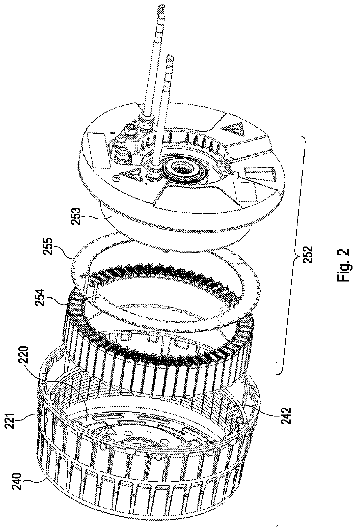
[0065]The configuration of the lead frame 255 will now be described, where in a first embodiment a single, substantially, circumferential lead frame, as illustrated in FIG. 5, is used for providing current from both control devices to the respective coil sets. As illustrated in FIG. 6 the substantially circumferential lead frame 255 is mounted to an axial mounting surface of a stator back-iron 600, which forms part of the stator 252, adjacent to the coils, where coils are wound on stator teeth formed on the stator back-iron 600.
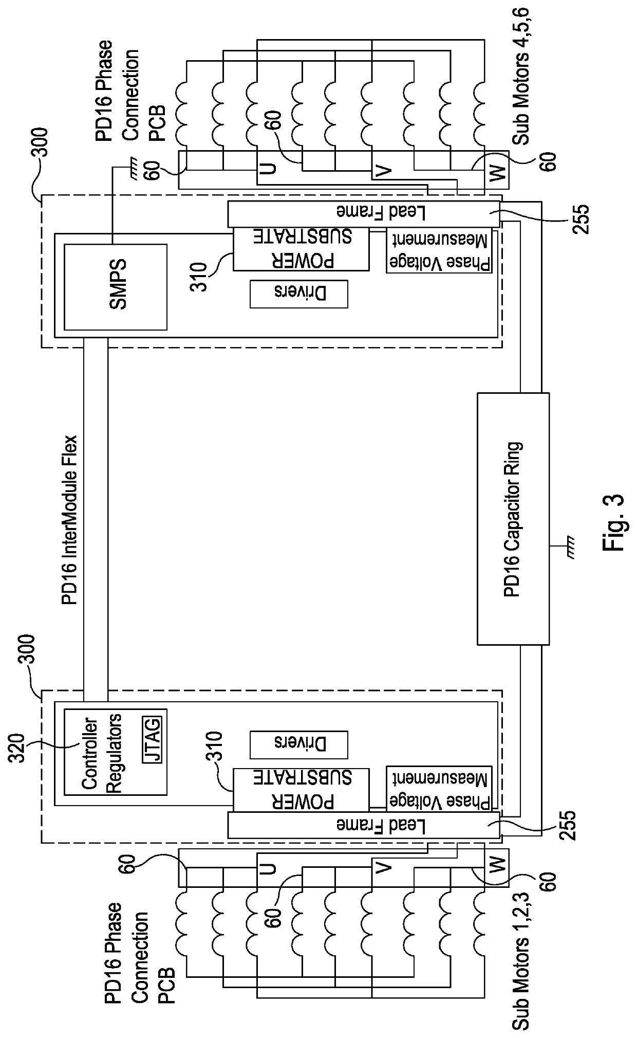
[0066]The lead frame 255 includes a first set of three apertures 610 for receiving a respective busbar lead frame pin for coupling the lead frame 255 to an inverter 310 in the first control device 300 and a second set of three apertures 620 for receiving a respective busbar lead frame pin for coupling the lead frame 255 to an inverter 310 in the second control device 300, as described below.
[0067]The lead frame 255 is mounted to the stator back-iron 600 via the
second embodiment
[0069]FIG. 7 illustrates the lead frame, where the lead frame comprises a first lead frame section 701 and a second lead frame section (not shown), where preferably both the first lead frame section 701 and the second lead frame section are semi-circumferential such that when mounted on the stator 252 the first lead frame section 701 and the second lead frame section form a substantially circumferential lead frame arrangement. As illustrated in FIG. 8 each lead frame section 701 is mounted to an axial mounting surface of a stator back-iron 600, which forms part of the stator 252, adjacent to the coils, where coils are wound on stator teeth formed on the stator back-iron 600.
[0070]Both the first lead frame section and the second lead frame section includes a set of three apertures 801 for receiving a respective busbar lead frame pin for coupling the first lead frame section 701 and the second lead frame section 701 to an inverter 310 in the first control device 300 and the second contro
PUM
 Abstract
Description
Claims
Application Information
 - R&D Engineer
- R&D Manager
- IP Professional
- Industry Leading Data Capabilities
- Powerful AI technology
- Patent DNA Extraction
Browse by: Latest US Patents, China's latest patents, Technical Efficacy Thesaurus, Application Domain, Technology Topic.
© 2024 PatSnap. All rights reserved.Legal|Privacy policy|Modern Slavery Act Transparency Statement|Sitemap