Self-propelled construction machine

a construction machine and self-propelled technology, applied in the direction of servomotors, ways, working accessories, etc., can solve the problems of ineffective counteraction, inability to effectively counteract, and inability to adjust the rotational speed of the travelling device only collectively, so as to improve the drive system of the travelling devi

Active Publication Date: 2021-06-24
WIRTGEN GMBH
View PDF0 Cites 0 Cited by
  • Summary
  • Abstract
  • Description
  • Claims
  • Application Information

AI Technical Summary

Benefits of technology

The technical effect of this patented invention is that it improves the driving systems for construction machines by making them more flexible and adaptable to different terrains or conditions.

Problems solved by technology

This patent describes different types of construction machines with pivotable traveling devices called work devices. These work devices have a hydraulic drive system that allows them to move towards the edges of the machine without getting stuck. However, there is a technical problem associated with the use of hydraulic drive systems in construction machines due to their size requirements. Specifically, the hydraulic drive system needs to be small enough to avoid interference from the hydraulics. Additionally, the hydraulic drive system requires a separate control valve for each traveling device, making it difficult to independently adjust the driving force applied to each device.

Method used


Image

  • Self-propelled construction machine
  • Self-propelled construction machine
  • Self-propelled construction machine

Examples


Embodiment Construction

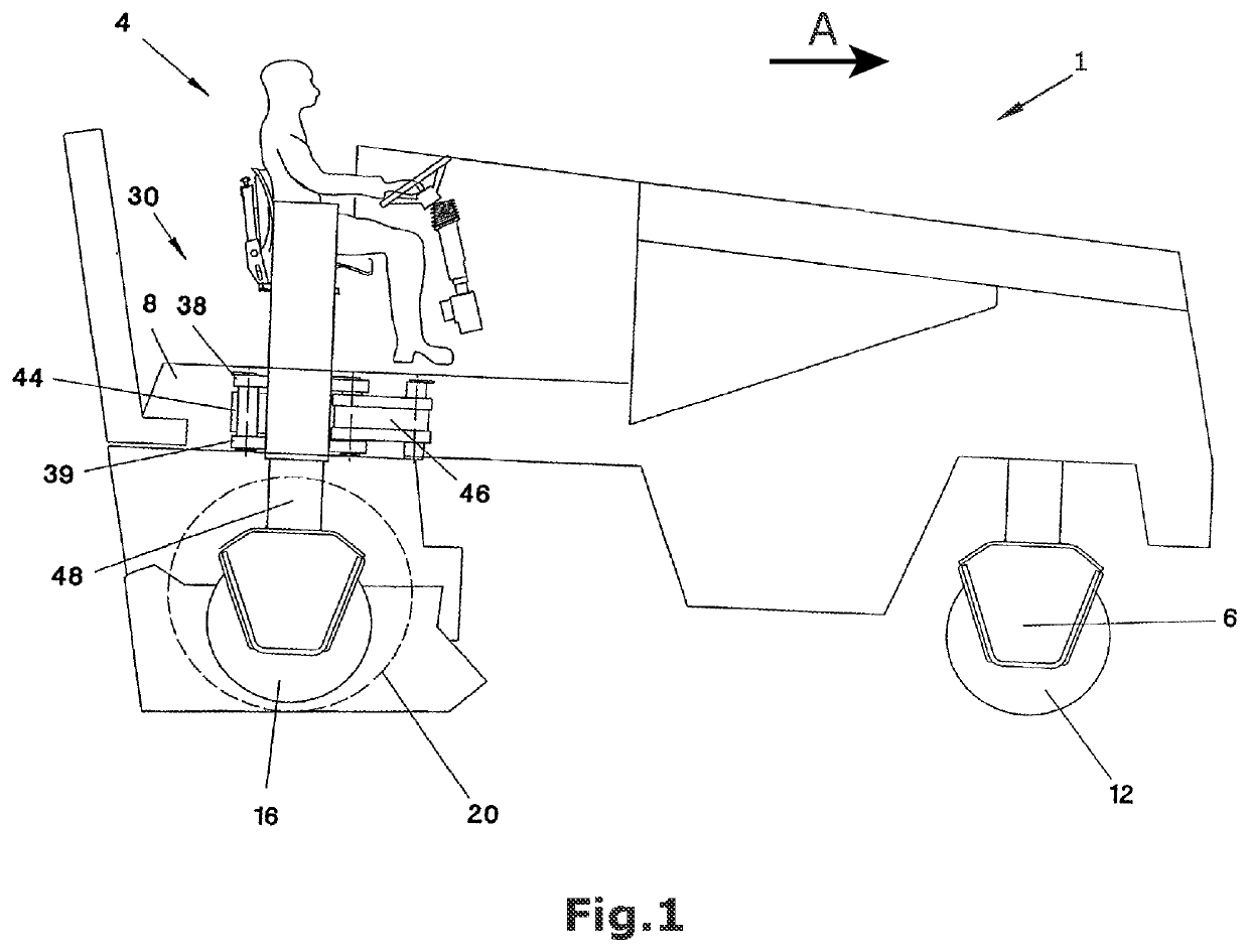
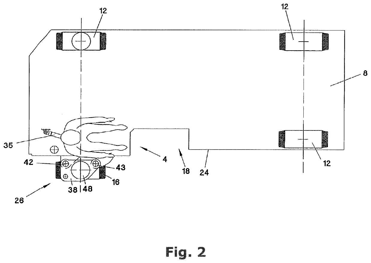
[0045]FIG. 1 shows a self-propelled construction machine 1. In the embodiment depicted, the self-propelled construction machine is a road milling machine. Said construction machine 1 comprises a machine frame 8 and at least three travelling devices 12, 16. The construction machine 1 depicted comprises two front 12 and two rear 12, 16 travelling devices, of which, in FIG. 1, the ground-engaging units arranged on the left side as seen in the direction of operation A are not visible. The travelling devices may be wheels, as in the embodiment depicted, or alternatively also tracked ground-engaging units.

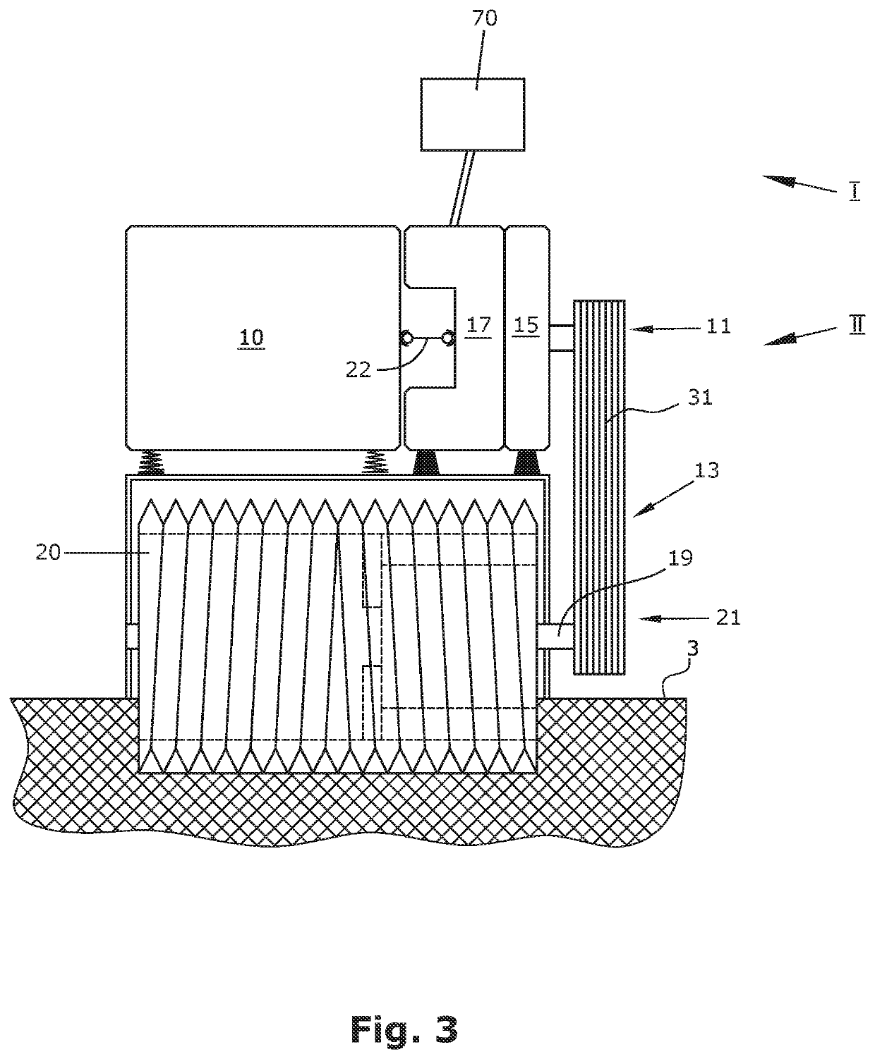
[0046]The travelling devices 12, 16 may each be driven by means of at least one hydraulic drive system 70. In a construction machine 1, at least two travelling devices may be driven, wherein, for example, the front travelling devices 12 may also be non-driven. At least one of the at least three travelling devices 12, 16 is realized as a pivotable travelling device 16. Said travelling device


PUM

PropertyMeasurementUnit
Timeaaaaaaaaaa
Volumetric flow rateaaaaaaaaaa

Abstract

In a self-propelled construction machine (1), in particular road milling machine, comprising a machine frame (8), at least three travelling devices (12, 16), wherein at least one of the three travelling devices (12, 16) is realized as a pivotable travelling device (16) so that said travelling device (16) is pivotable about at least one vertical pivoting axis in relation to the machine frame (8) between a first pivoted-in and at least one second pivoted-out position, at least one working device (20), in particular a milling drum, for working the ground pavement (3), at least one hydraulic drive system (70) for driving at least two travelling devices (12, 16), wherein at least one of the at least two driven travelling devices is the pivotable travelling device (16), wherein the hydraulic drive system (70) comprises at least one hydraulic pump (78), it is provided for the following features to be achieved: the hydraulic drive system (70) comprises one each hydraulic variable displacement motor (72) for driving the driven travelling devices (12) with the exception of the at least one pivotable travelling device (16), wherein the hydraulic drive system (70) comprises a hydraulic fixed displacement motor (74) for driving the at least one pivotable travelling device (16).

Description


Claims


Application Information

Patent Timeline
Owner WIRTGEN GMBH
Why Eureka
Try Eureka