Preparation process for graphene resonant gas sensor based on doped metal atoms

a technology metal atoms, applied in the field of sensors, can solve the problems of poor contact, low sensitivity, etc., and achieve the effect of low sensitivity and low quality of graphene resonant gas sensors

Active Publication Date: 2021-08-26
JIANGSU UNIV
View PDF0 Cites 0 Cited by
  • Summary
  • Abstract
  • Description
  • Claims
  • Application Information

AI Technical Summary

Benefits of technology

The inventors have developed an improved method for creating high-quality nanoparticles called quantum dots (QDS) within specific areas inside or near certain materials like carbon fibers. This allows Qds to absorb light at different wavelengths while also being able to detect it accurately without losing their effectiveness due to poor absorption caused by other molecules nearby.

Problems solved by technology

The technical problem addressed in this patented text relates to developing an improved type of gas sensor with better performance without being too expensive or bulky due to its use of traditional methods like electrodes made from materials containing carbons (graphite) alone.

Method used


Image

  • Preparation process for graphene resonant gas sensor based on doped metal atoms
  • Preparation process for graphene resonant gas sensor based on doped metal atoms
  • Preparation process for graphene resonant gas sensor based on doped metal atoms

Examples


embodiment 1

[0033]Specific implementation steps are as follows:

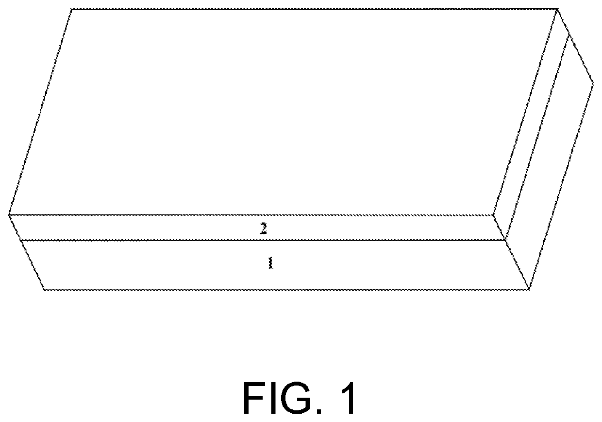
[0034]Step 1: a SiO2 dielectric layer 2 having a thickness of 100 nm is deposited on a Si substrate 1 by a CVD method, as shown in FIG. 1. Then, a ultrasonic cleaning is performed on the SiO2 dielectric layer 2 by using absolute ethanol and deionized water, where the ultrasonic power is 30 to 45 W, and the cleaning time is 3 to 5 minutes.

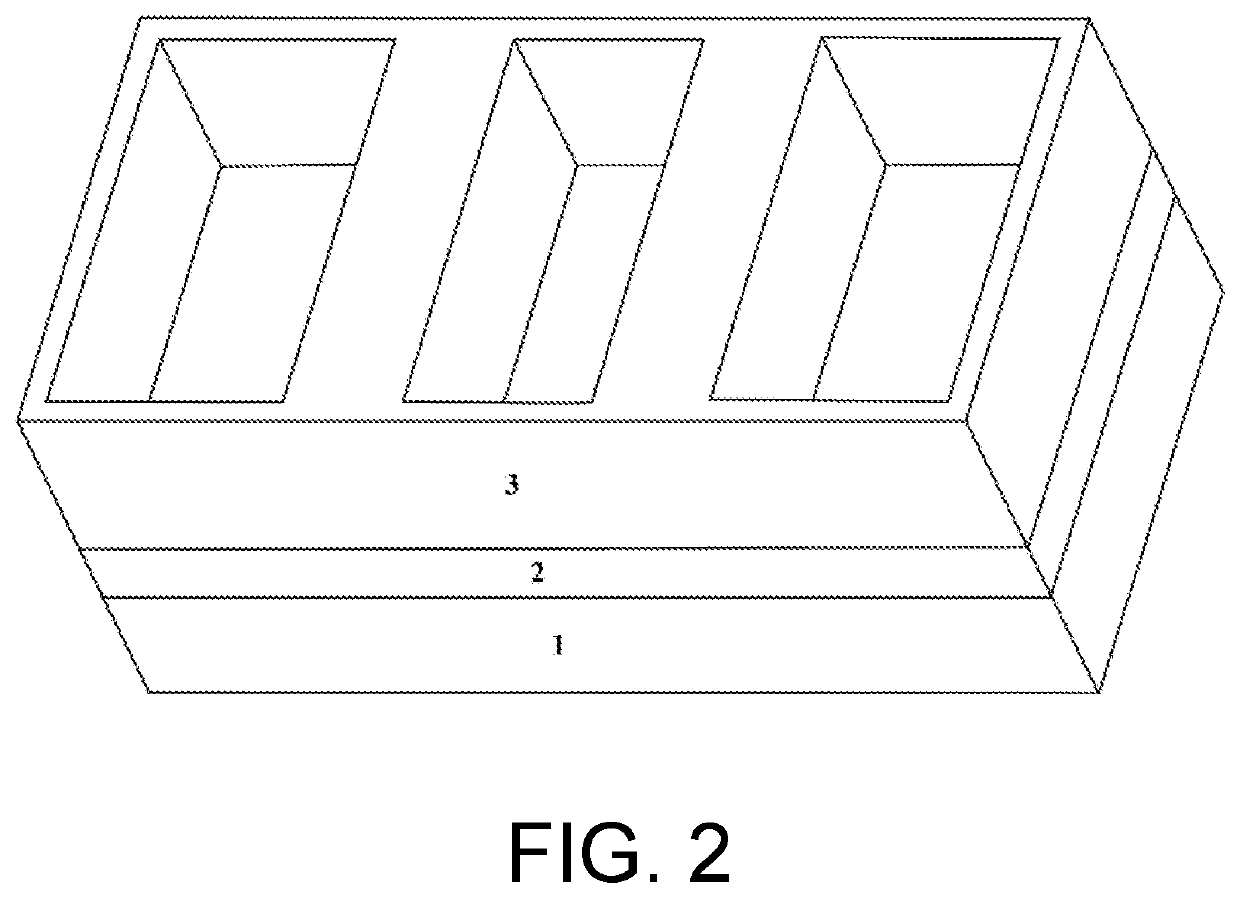
[0035]Step 2: a PPA having a thickness of 1000 nm is spin-coated on the surface of the SiO2 dielectric layer 2, where the type of the PPA is poly(phthalaldehyde), the viscosity of the PPA is 5 cp, the rotation speed of a spin-coater is 1000 to 2000 r / min, and the spin-coating time is 30 s. Three rectangular grooves are etched in the PPA by using a direct writing machine having a nano 3D structure, where for the three rectangular grooves, depths of the grooves are all 1000 nm; lengths of grooves on two sides are both 1000 nm, and widths of grooves on two sides are both 1000 nm; a length of a middle gr


PUM


Abstract

The present disclosure belongs to the technical field of sensors, relates to a graphene resonant gas sensor, and in particular, to a graphene resonant gas sensor based on doped metal atoms and a preparation process therefor. In the present disclosure, the metal atoms are embedded in a graphene resonant beam, and a transition metal layer may use the doped metal atoms as anchor points to be tightly adsorbed to the surface of the graphene resonant beam, so that the quality of surface contact between the transition metal layer and the graphene resonant beam is improved, and the problems such as low quality and low sensitivity of conventional resonant gas sensors are effectively solved.

Description


Claims


Application Information

Patent Timeline
Owner JIANGSU UNIV
Why Eureka
Try Eureka