Optical transceiver module and optical cable module

Active Publication Date: 2021-10-28
YU SHENG PHOTOELECTRIC CO LTD
View PDF0 Cites 6 Cited by
  • Summary
  • Abstract
  • Description
  • Claims
  • Application Information

AI Technical Summary

Benefits of technology

The present invention is about an optical transceiver module that is designed to be compact. This means that it utilizes its internal space effectively to achieve a small size.

Problems solved by technology

However, conventional electrical I / O (input / output) signaling is not expected to keep pace with the demand for performance increases, especially for a higher performance computing expectations.
Therefore, electrical I / O signal rates are limited by the electrical characteristics of the electrical connectors.
However, in recent years, the optical modules such as optical transceiver are required to be further down-sized.

Method used


Image

  • Optical transceiver module and optical cable module
  • Optical transceiver module and optical cable module
  • Optical transceiver module and optical cable module

Examples


Embodiment Construction

[0038]The following embodiments are referring to the accompanying drawings for exemplifying specific implementable embodiments of the present invention. Furthermore, directional terms described by the present invention, such as upper, lower, front, back, left, right, inner, outer, side, etc., are only directions by referring to the accompanying drawings, and thus the used directional terms are used to describe and understand the present invention, but the present invention is not limited thereto.

[0039]The drawings and description are to be regarded as illustrative in nature and not restrictive. Like reference numerals designate like elements throughout the specification. In addition, the size and thickness of each component shown in the drawings allow ease of understanding and ease of description, but the present invention is not limited thereto.

[0040]In the drawings, the thickness of layers, films, panels, regions, etc., are exaggerated for clarity. In the drawings, for understandi...


PUM


Abstract

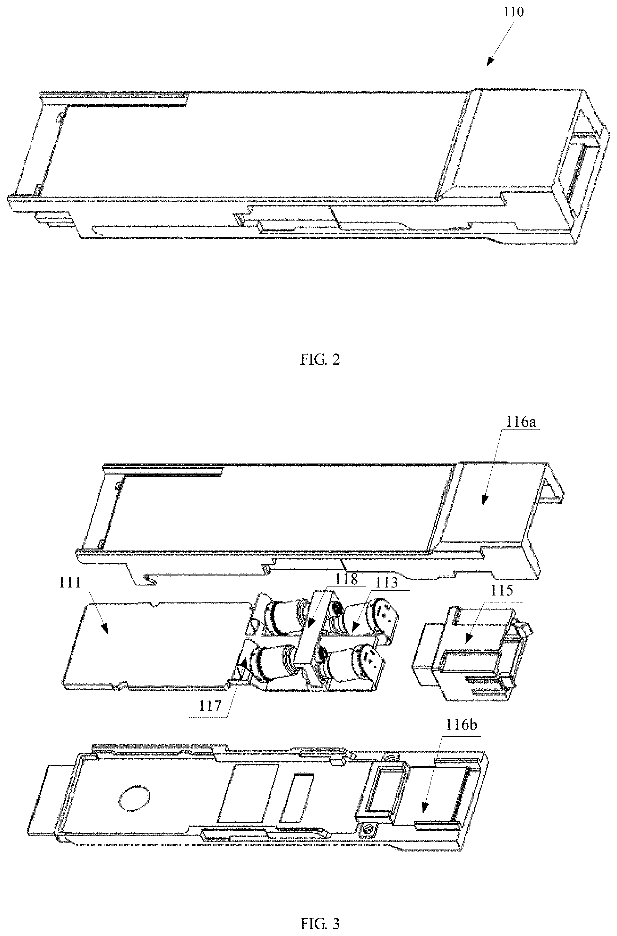
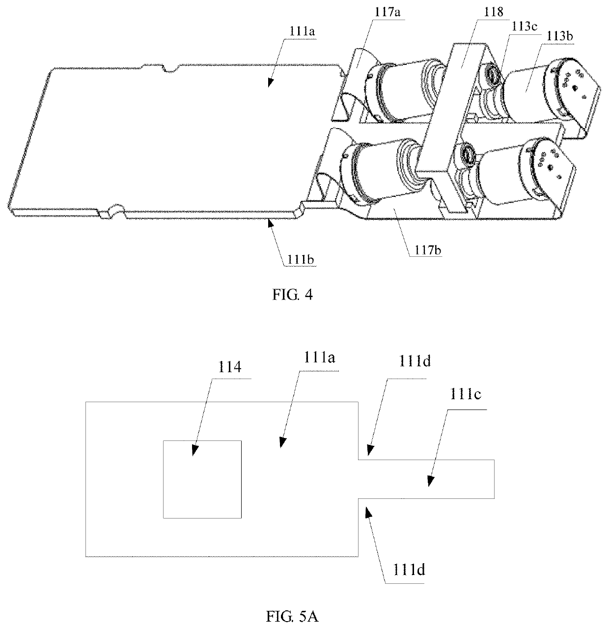
An optical transceiver module and an optical cable module using the same are provided. The optical transceiver module: a substrate; at least one optical receiving device connected to the substrate; a plurality of optical transmitting devices connected to the substrate, wherein the optical transmitting devices comprise a plurality of first optical transmitting devices and a plurality of second optical transmitting devices, and the optical transmitting devices are misaligned to each other.

Description

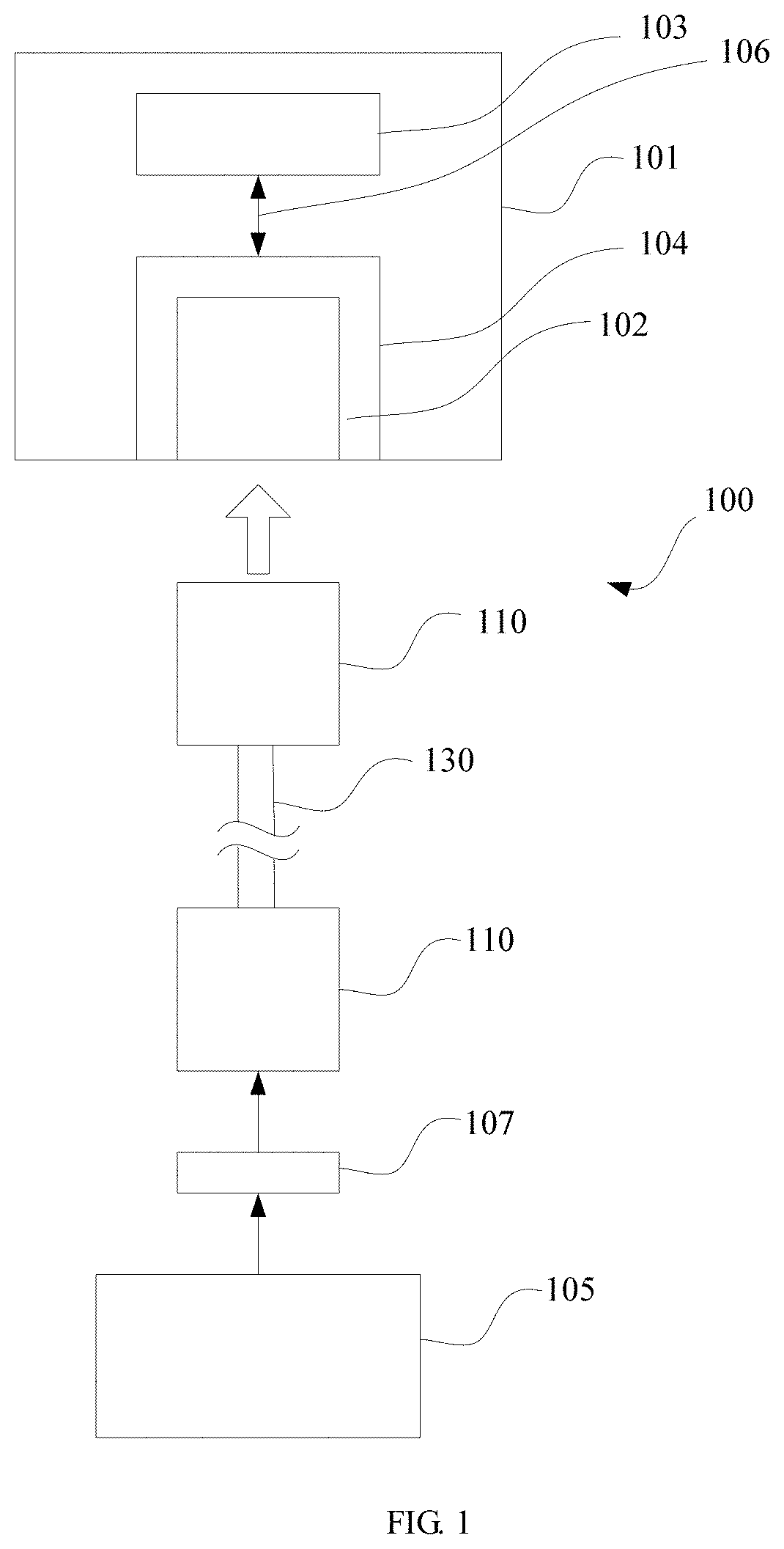
FIELD OF THE INVENTION[0001]The present invention relates to an optical fiber communication technology field, and in particularly, to an optical transceiver module and an optical cable module using the same.BACKGROUND OF THE INVENTION[0002]In the optical fiber communication technology, it is necessary to convert electrical signals into optical signals through an optical transceiver module (such as a laser device), and then to couple the optical signals into an optical fiber for transmitting. At present, the demand for computing devices continues to rise, even as the demand for computing devices to achieve higher performance also rises. However, conventional electrical I / O (input / output) signaling is not expected to keep pace with the demand for performance increases, especially for a higher performance computing expectations. Currently, I / O signals are sent electrically to and from the processor through the board and out to peripheral devices. Electrical signals must pass through so...

Claims


Application Information

Patent Timeline
IPC IPC(8): G02B6/42
CPCG02B6/4284G02B6/4234G02B6/4271G02B6/4246G02B6/4292G02B6/4249G02B6/4204G02B6/4296H01S5/024G02B6/4268H01S5/183
Inventor CHANG, CHUN-YANGLU, CHENG-HUNGWU, CHANG-CHERNG
Owner YU SHENG PHOTOELECTRIC CO LTD
Why Eureka
Try Eureka