Imaging and pressure sensing apparatus and probes with a slidable sheath

Pending Publication Date: 2022-05-05
KOTL LLC
View PDF7 Cites 0 Cited by
  • Summary
  • Abstract
  • Description
  • Claims
  • Application Information

AI Technical Summary

Problems solved by technology

However, the introduction of the pressure sensor causes partial occlusion of the blood vessel.
This occlusion causes more pressure drop in the stenosis due to smaller luminal profile, which in turn causes errors in the FFR measurement.
However, compared to a single modality probe, this side-by-side arrangement results in an undesirable larger crossing profile.
If the combined probe is inserted through the stenosis to measure distal pressure, it will occlude an even larger portion of the lumen, which may further affect the accuracy of FFR measurement.
However, because OCT involves coherent imaging, OCT typically requires a single-mode fiber.
Unfortunately, single-mode fiber has a very small core diameter and often a small numerical aperture.
Consequently, light reflected from only a small portion of the FFR pressure transducer can be collected by the single-mode fiber, which leads to a low signal-to-noise ratio (SNR) and requires a very meticulous, and therefore expensive, alignment process during probe manufacture.

Method used


Image

  • Imaging and pressure sensing apparatus and probes with a slidable sheath
  • Imaging and pressure sensing apparatus and probes with a slidable sheath
  • Imaging and pressure sensing apparatus and probes with a slidable sheath

Examples


Example

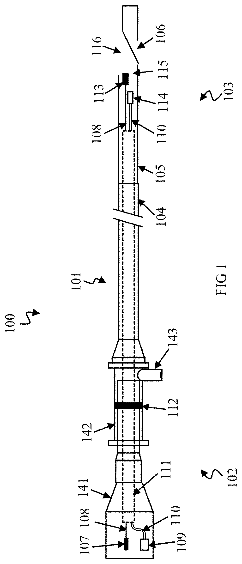
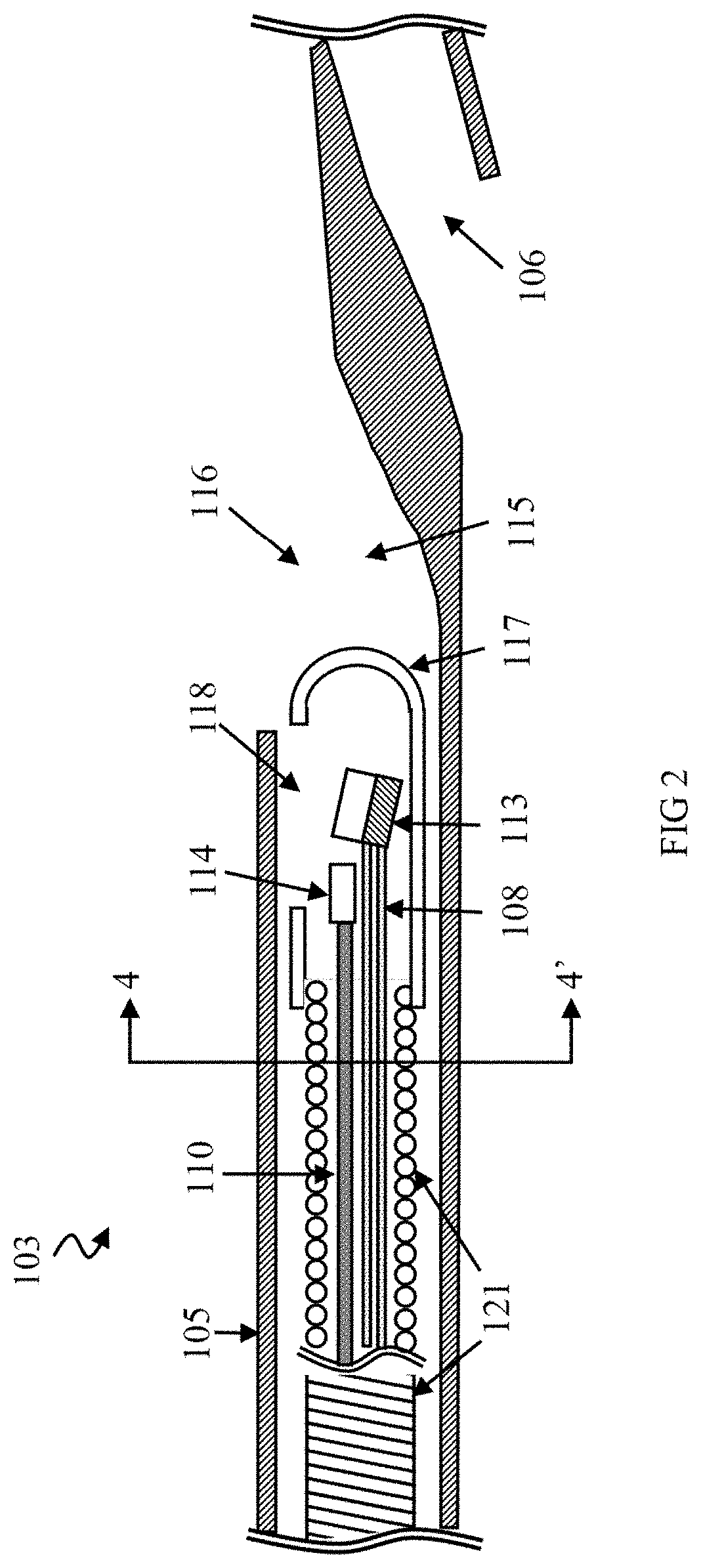
[0024]The following description refers to the accompanying drawings that illustrate certain embodiments of the invention in more detail. FIG. 1 provides an overall view of a specific imaging and pressure sensing combination probe 100 according to one specific embodiment of the present invention in the specific form of a catheter for easy insertion into a lumen of an imaging patient such as a blood vessel. The probe 100 includes a probe sheath 101 with a sheath proximal end 102 and a sheath distal end 103 where a proximal end outer boundary 104 transitions to a distal end inner boundary 105. The probe sheath 101 can be made of materials with substantially little attenuation in the mechanical frequency band used for ultrasound imaging.

[0025]The sheath proximal end 102 here includes a pressure connector 109, an imaging connector 107, a proximal mating unit 141, a telescoping section 142 and a liquid purge port 143. The imaging connector or the pressure connector can be either optical conn


PUM


Abstract

The invention relates to a medical sensor system with a probe sheath with a sheath distal end configured for insertion through an insertion opening into a lumen of a patient. A pressure signal channel between the sheath ends contains a pressure sensor at the sheath distal end configured to measure pressure in the pressure signal channel and produce a corresponding pressure measurement signal. A sheath retraction mechanism portion of the probe sheath has: i. an extended sheath configuration wherein the sheath distal end extends through the insertion opening into the lumen and encloses the pressure measurement sensor in physical isolation from the lumen, and ii. a retracted sheath configuration wherein the sheath distal end is longitudinally retracted back from the lumen towards the insertion opening so as to expose at least a portion of the pressure measurement sensor to the lumen.

Description


Claims


Application Information

Patent Timeline
Owner KOTL LLC
Why Eureka
Try Eureka