Battery separator
a battery separator and separator technology, applied in cell components, alkaline accumulators, electrical equipment, etc., can solve the problems of separator breakage, poor battery yield, short circuit, etc., and achieve tensile strength and bending resistance improvement, the effect of hardly causing a short circui
- Summary
- Abstract
- Description
- Claims
- Application Information
AI Technical Summary
Benefits of technology
Problems solved by technology
Method used
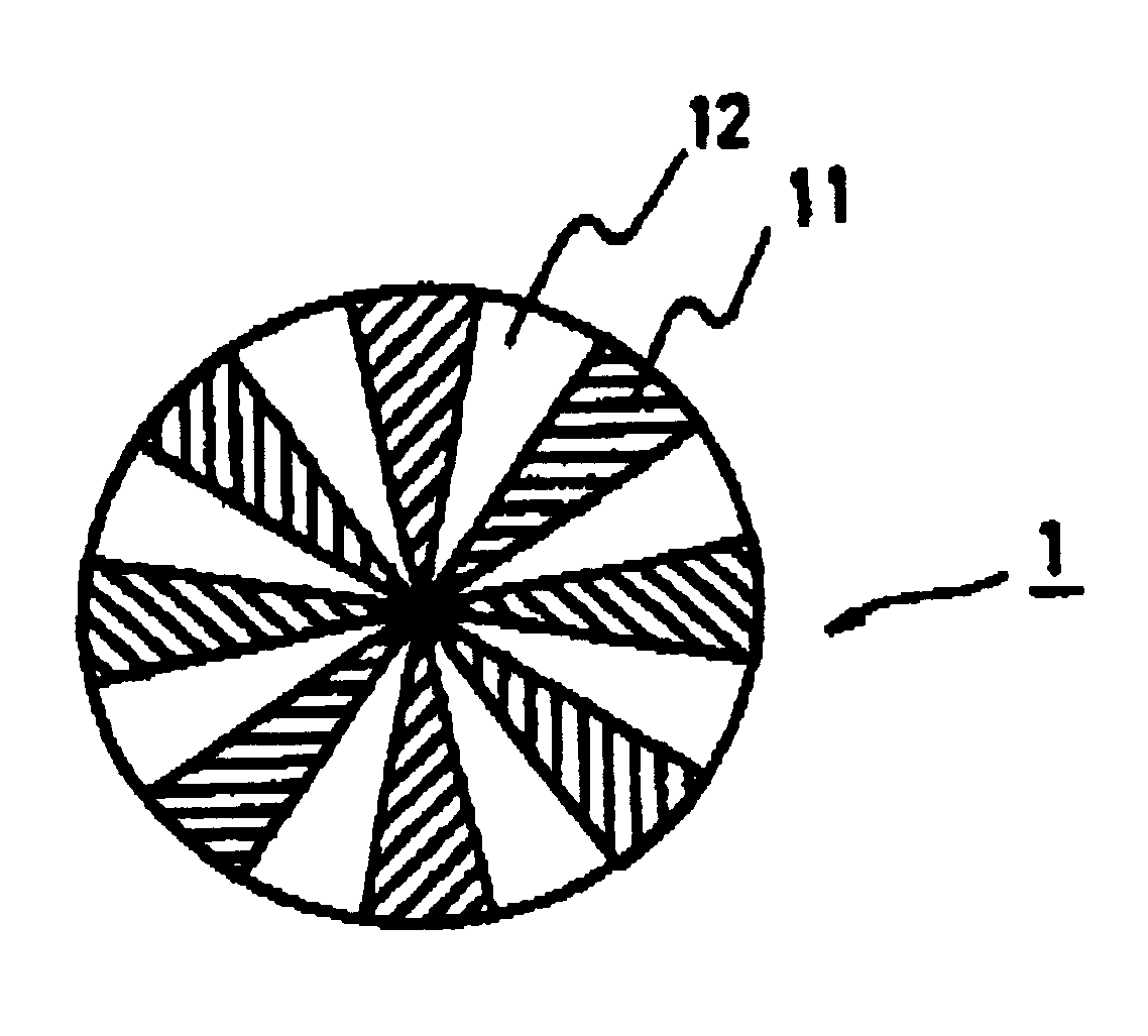
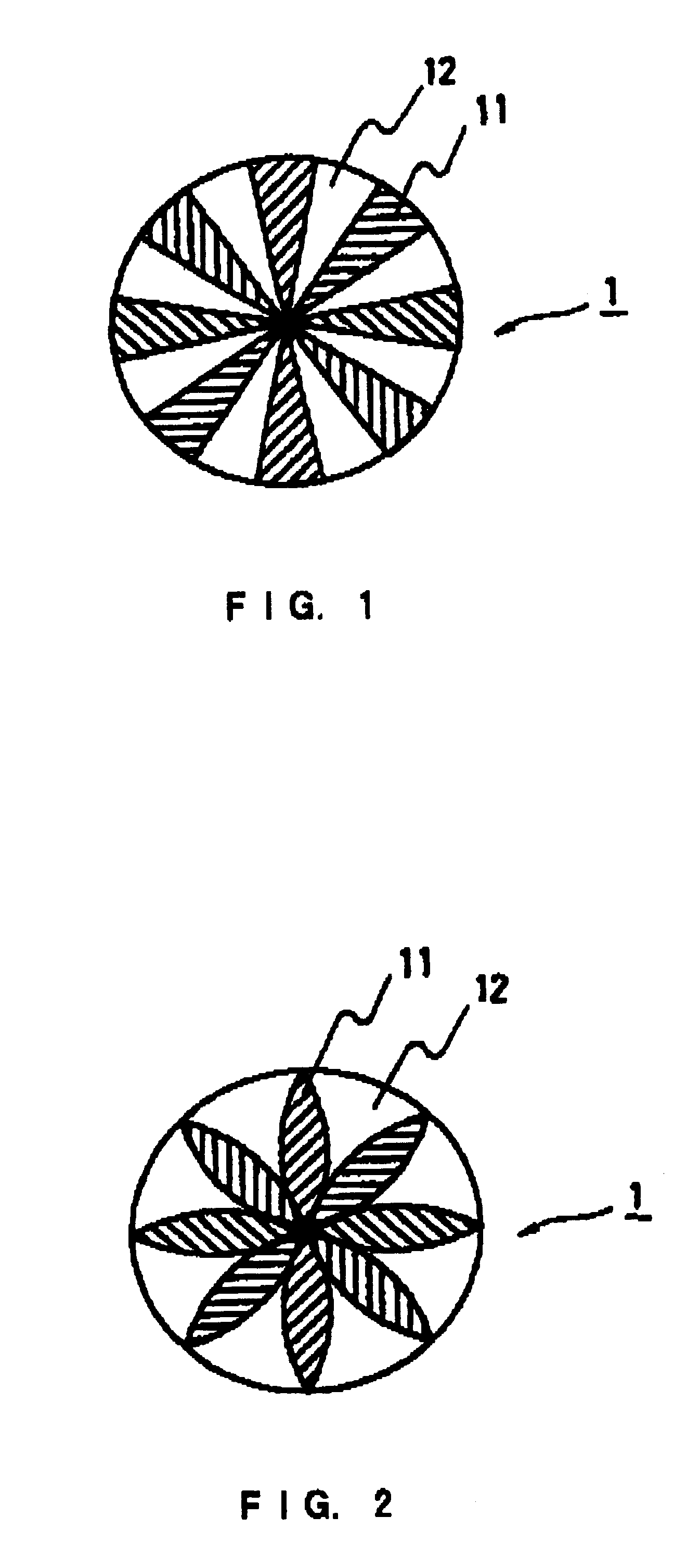
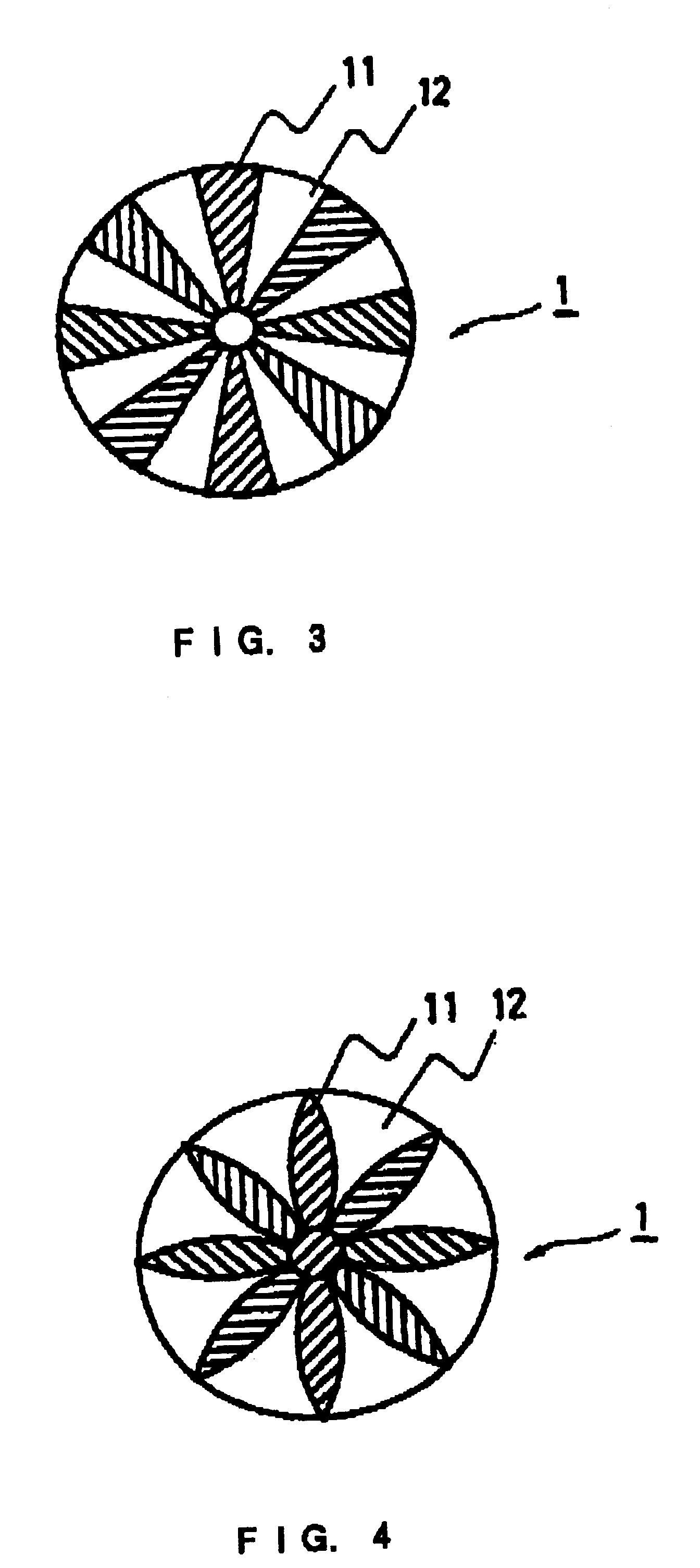
Image

Examples
example 2
The operation of Example 1 was repeated except that a fiber web was formed by a conventional wet-laid web-forming method from a slurry prepared by mixing and dispersing
(i) 40 mass % of high Young's modulus polypropylene fibers (melting point: 174.degree. C.; fineness=1.2 denier (fiber diameter=13.7 .mu.m); fiber length=10 mm; tensile strength=12 g / d; Young's modulus=850 kg / mm.sup.2 and thermal shrinkage ratio=7%) manufactured in the same manner as in Example 1 and
(ii) 60 mass % of sheath-core type fusible fibers (fineness 1.1 denier (fiber diameter=13.1 .mu.m); fiber length=5 mm; and tensile strength=3.5 g / d) wherein the core component was polypropylene while the sheath component (low-melting component) was high-density polyethylene (melting point: 135.degree. C.) similarly to Example 1. As a result, a separator (mass per unit area=60 g / m.sup.2 ; and thickness=0.15 mm) was manufactured.
example 3
The operation of Example 1 was repeated except that a hydrophilization was carried out by dipping a fused nonwoven fabric for 10 minutes into a 39.degree. C. fuming sulfuric acid solution (15% SO.sub.3 solution) to manufacture a separator (mass per unit area=60 g / m.sup.2 ; and thickness=0.15 mm).
example 4
A fiber web was manufactured by a conventional wet-laid web-forming method from a slurry prepared by mixing and dispersing
(i) 30 mass % of high Young's modulus polypropylene fibers (melting point: 174.degree. C.; fineness=1.2 denier (fiber diameter=13.7 .mu.m); fiber length=10 mm; tensile strength=12 g / d; Young's modulus=850 kg / mm.sup.2 ; and thermal shrinkage ratio=7%) manufactured in the same manner as in Example 1 and
(ii) 70 mass % of sheath-core type fusible fibers (fineness=0.7 denier (fiber diameter=10.4 .mu.m); fiber length=5 mm; and tensile strength=3.5 g / d) where the core component was polypropylene while the sheath component low-melting component) was high-density polyethylene (melting point: 135.degree. C.).
Then this fiber web was heated for 10 seconds by an oven set to the temperature of 135.degree. C., and immediately thereafter pressurized (2.5 N / cm) by a water-cooled cooling roll to manufacture a fused nonwoven fabric wherein the fibers were fused with the sheath
PUM
 Abstract
Description
Claims
Application Information
 - R&D Engineer
- R&D Manager
- IP Professional
- Industry Leading Data Capabilities
- Powerful AI technology
- Patent DNA Extraction
Browse by: Latest US Patents, China's latest patents, Technical Efficacy Thesaurus, Application Domain, Technology Topic.
© 2024 PatSnap. All rights reserved.Legal|Privacy policy|Modern Slavery Act Transparency Statement|Sitemap