Method for reworking a multi-layer photoresist following an underlayer development

Inactive Publication Date: 2005-03-29
GLOBALFOUNDRIES INC
View PDF12 Cites 29 Cited by
  • Summary
  • Abstract
  • Description
  • Claims
  • Application Information

AI Technical Summary

Benefits of technology

A portion of the protection layer and the imaging layer are then removed in a generally concurrent fashion while leaving a portion of the protection layer over the exposed process layer. For example, such removal may comprise a low selectivity etch with respect to the protection layer and the imaging layer. In so doing, the removal of the imaging layer does not adversely impact the process layer due to the remaining portion of the protection layer lying thereover. The re-work process then continues with a concurrent removal of the remaining portion of the protection layer and the underlying layer of the multi-layer resist, for example, via an etch which is selective with respect to the underlying process layer. In the above manner, the protection layer and the underlying layer are substantially completely removed without damage to the process layer, thereby allowing for a new photoresist to be formed thereover.

Problems solved by technology

If, however, defects are found associated with the patterned multi-layer resist, a re-work of the resist is performed.

Method used


Image

  • Method for reworking a multi-layer photoresist following an underlayer development
  • Method for reworking a multi-layer photoresist following an underlayer development
  • Method for reworking a multi-layer photoresist following an underlayer development

Examples


Example

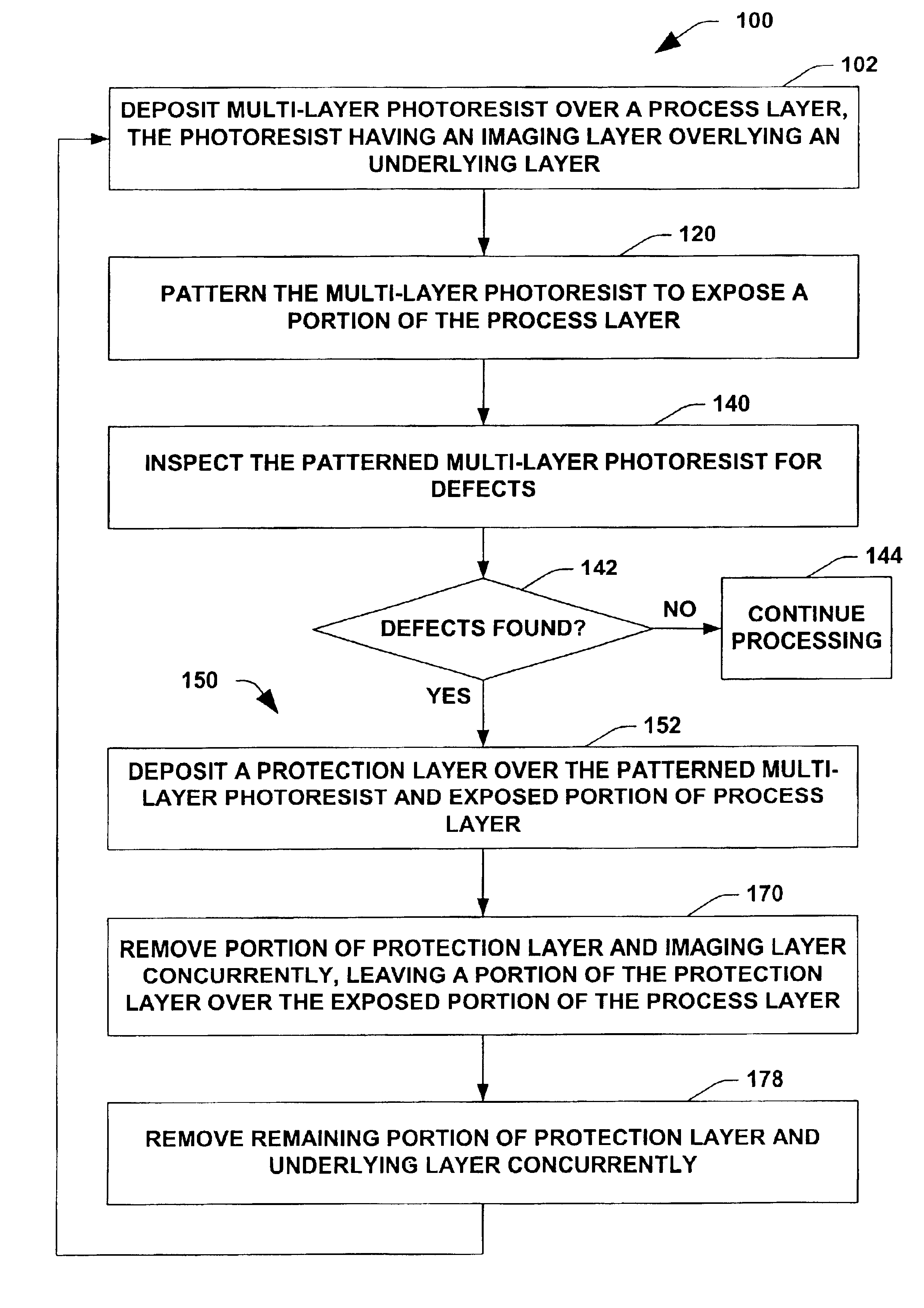
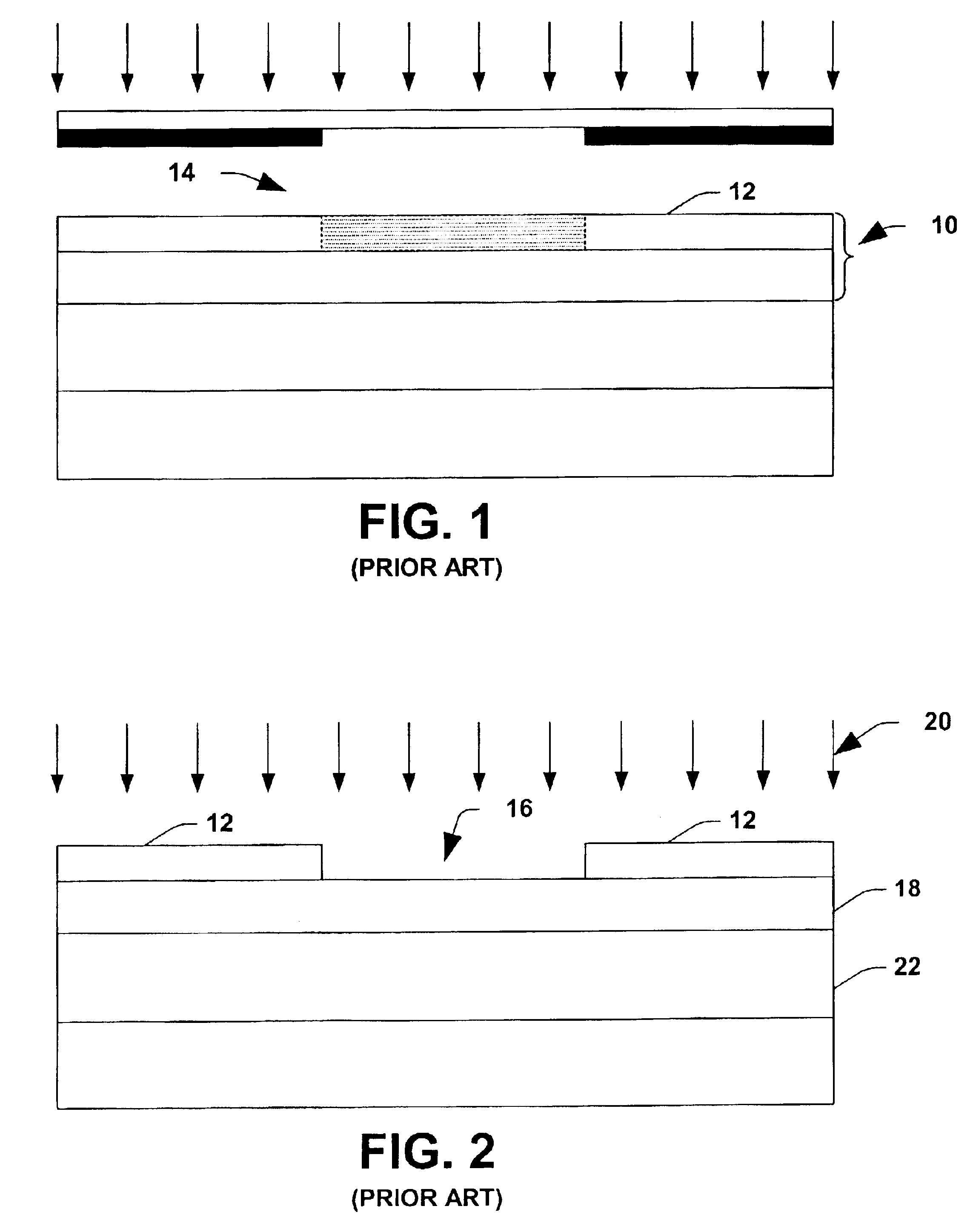
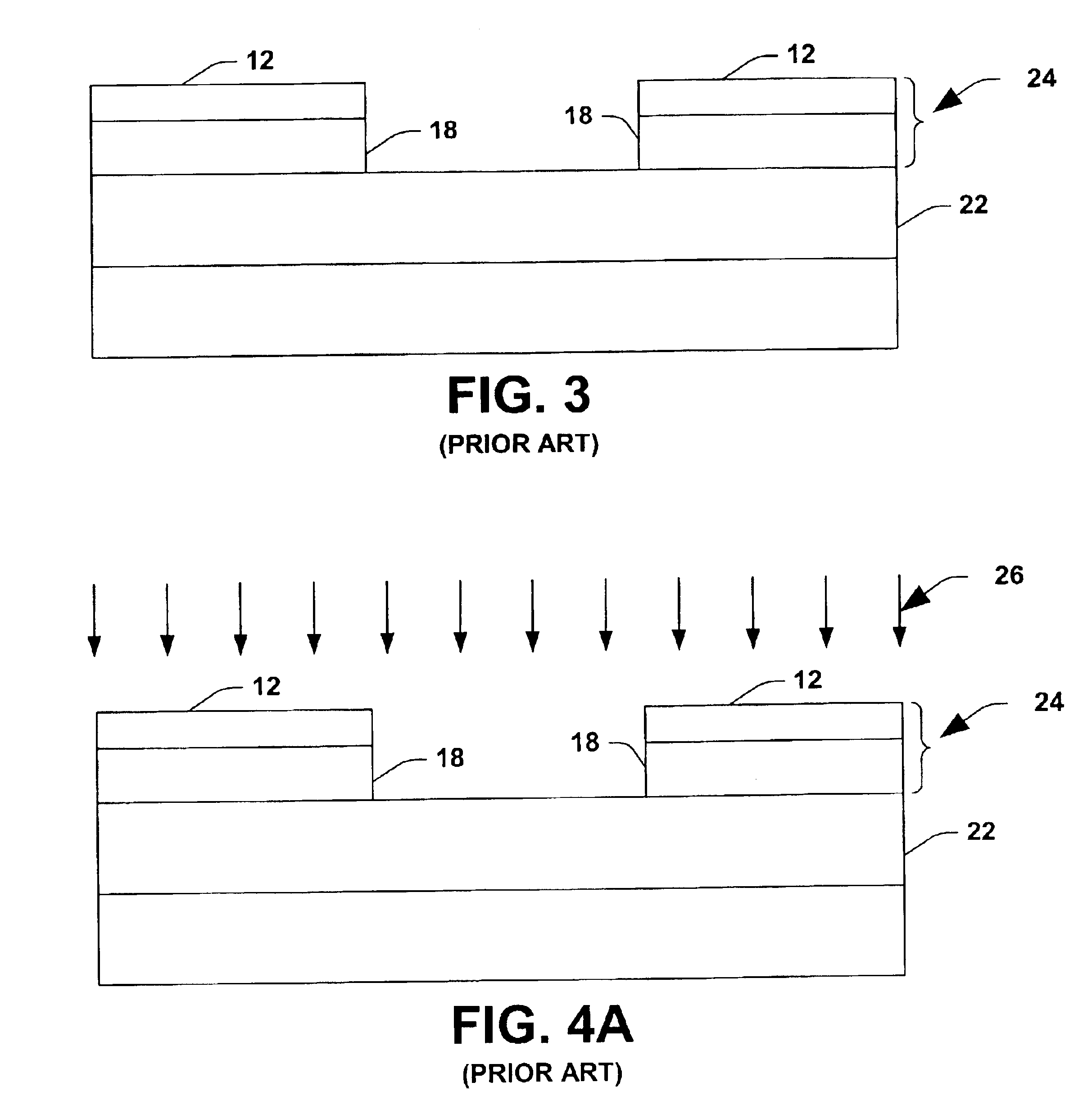
The following is a detailed description of the present invention made in conjunction with the attached Figures, wherein like reference numerals will refer to like elements throughout. The present invention is directed to a method of re-working a multi-layer photoresist. After patterning the photoresist, a portion of an underlying process layer is exposed therethrough and the resist is inspected for defects. Upon an affirmative identification of a defect, the patterned multi-layer photoresist (which comprises an underlying layer covered by an imaging layer) is covered with a protection layer, which also covers the exposed portion of the process layer. The protection layer and imaging layer are then removed in a generally concurrent fashion, after which a portion of the protection layer still resides over the exposed process layer. The underlying layer and remaining protection layer are then removed in a generally concurrent fashion. The re-work methodology of the present invention advan


PUM


Abstract

A method of processing a semiconductor device is disclosed and comprises patterning a multi-layer photoresist which comprises an imaging layer overlying an underlying layer. The patterning of the resist defines an exposed portion of an underlying process layer. The method further comprises inspecting the patterned multi-layer photoresist for defects and re-working the patterned multi-layer photoresist upon a failed inspection. The re-work process comprises depositing a protection layer over the patterned multi-layer photoresist and over the exposed portion of the underlying process layer. A portion of the protection layer and the imaging layer are then removed in a concurrent manner while leaving a remaining portion of the protection layer covering the exposed portion of the underlying process layer. A remaining portion of the protection layer and the underlying layer are then removed in a concurrent manner and such removal does not adversely impact the process layer.

Description


Claims


Application Information

Patent Timeline
Owner GLOBALFOUNDRIES INC
Why Eureka
Try Eureka