Control device and control program product for engine

a control device and engine technology, applied in the direction of electric control, ignition automatic control, machines/engines, etc., can solve the problems of slow engine rotation speed and adverse stalling, delay in moving the cam position incurs a hunting of engine rotation, and the air-fuel mixture especially in the small intake amount may not be sufficiently obtained

Active Publication Date: 2006-01-24
SUZUKI MOTOR CORP
View PDF6 Cites 5 Cited by
  • Summary
  • Abstract
  • Description
  • Claims
  • Application Information

AI Technical Summary

Benefits of technology

The technical effect of this patented technology is that it allows engines with different lifts or lash adjustments to have consistently controlled valves without being affected even if they are at very low temperatures due to their continuous variation over time. This can improve performance and reduce fuel consumption during operation compared to traditional methods like hydraulic pump systems.

Problems solved by technology

The technical problem addressed in this patented technology relating to valves (intake systems) are how to reduce friction during operation while maintaining efficient combustion performance without sacrificing power delivery. This requires precise adjustment over different flight characteristics depending on whether it's going from light loads to heavy ones.

Method used


Image

  • Control device and control program product for engine
  • Control device and control program product for engine
  • Control device and control program product for engine

Examples


Embodiment Construction

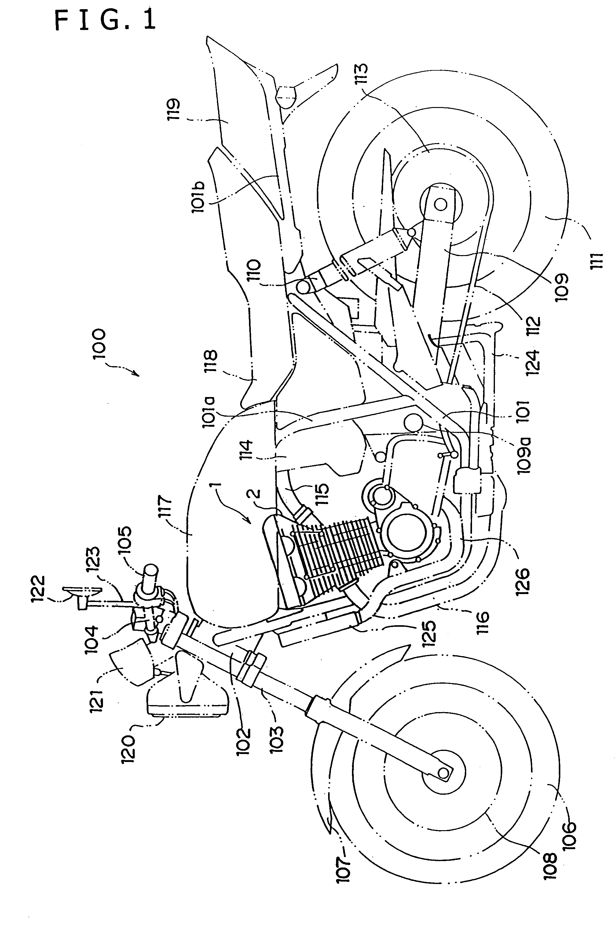
[0030]Hereinafter, a preferred embodiment according to the present invention will be described based on the drawings. In the present embodiment, an example of calculating a target cam position based on the cooling water temperature in an idling engine will be given. A control device for an engine according to the present invention is efficiently applicable to various types of gasoline engines used in motorcycles or automobiles. In this embodiment, a motorcycle engine, as shown in FIG. 1, is taken as an example.

[0031]First, the entire structure of a motorcycle 100 concerning the present embodiment will be described. In FIG. 1, two front forks 103 supported rotatably clockwise and counterclockwise by a steering head pipe 102 are provided at the front of a vehicle body frame 101 made of steel or aluminum alloy material. A handle bar 104 is fixed to the top of the front forks 103, and is equipped with grips 105 at both ends.

[0032]A front wheel 106 is rotatively supported at the lower part


PUM


Abstract

An engine unit includes a valve driving mechanism in which a cam having its cam profile axially varying continuously is slid along the axis of the cam shaft to control continuously a lift characteristic of an intake valve to be steplessly variable. In the control device of the engine, when the engine is, determined to be in a idling state by an idling-state determining unit, a target cam position is obtained according to a target valve lift amount calculated based on the cooling water temperature by a target cam position calculated unit, and the target cam position is corrected according to atmospheric pressure, an engine oil temperature, an ATF temperature, and an intake temperature, so that an engine rotation will be stabilized in the idling state.

Description


Claims


Application Information

Patent Timeline
Owner SUZUKI MOTOR CORP
Why Eureka
Try Eureka