Negative pressure material tank

A technology of negative pressure material and tank body, applied in the field of negative pressure material tank, can solve the problem of reducing the effective volume of material tank, and achieve the effect of convenient material suction

Pending Publication Date: 2021-06-04
HEBEI AGRICULTURAL UNIV.
View PDF0 Cites 0 Cited by
  • Summary
  • Abstract
  • Description
  • Claims
  • Application Information

AI Technical Summary

Benefits of technology

This patented technology allows for efficient use of space while minimizing the risk of contamination during loading or unloading operations without requiring any special equipment like carts. By utilising this system, containers may hold many different types of material such as bottles containing liquids that require vacuum levels. Additionally, it provides a way to easily change how much liquid needs to be stored inside each container instead of having them stand out from other storage areas.

Problems solved by technology

This patented technology describes an improved design that allows for more efficient use of space while maintaining consistence between different types of materials during storage or transportation processes.

Method used


Image

  • Negative pressure material tank
  • Negative pressure material tank
  • Negative pressure material tank

Examples


Embodiment Construction

[0021] The following will clearly and completely describe the technical solutions in the embodiments of the present invention with reference to the accompanying drawings in the embodiments of the present invention. Obviously, the described embodiments are only some, not all, embodiments of the present invention. Based on the embodiments of the present invention, all other embodiments obtained by persons of ordinary skill in the art without making creative efforts belong to the protection scope of the present invention.

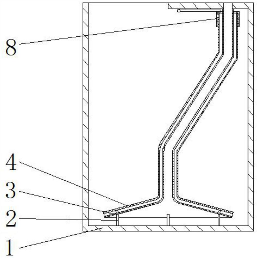
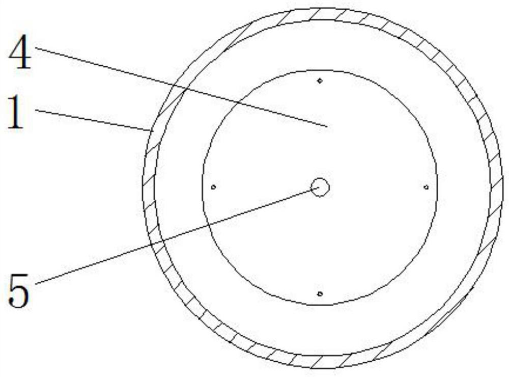
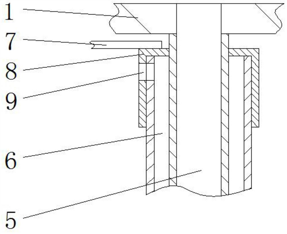
[0022] see Figure 1-3 , the present invention provides a technical solution: a negative pressure material tank, comprising a tank body 1 and an air intake pipe 6, an air intake pan 4 is arranged inside the tank body 1, and a suction pan 3 is arranged inside the air intake pan 4 , the air inlet plate 4 forms a connection structure between the adjustable fulcrum 2 and the suction plate 3, and the adjustable fulcrum 2 is distributed in a circle with the center line


PUM


Abstract

The invention discloses a negative pressure material tank comprising a tank body and a gas inlet pipe, a gas inlet disc is arranged in the tank body, a material suction disc is arranged on the inner side of the gas inlet disc, and adjustable fulcrums are fixed to the lower end of the material suction disc. Compared with an existing ordinary material tank, when the negative pressure material tank works, negative pressure is generated in the tank body, dust diffusion can be effectively prevented, the environment is protected, energy and raw materials are saved, the material suction area of a material suction pipe is increased through the material suction disc, the situation that a traditional material tank conducts concentration through gravity and vibration to facilitate material suction is not needed, and the lower portion of the tank body does not need to be made into a slope. When the traditional material tank and the negative pressure material tank occupy the same space, the volume of the lower portion of the traditional material tank is only one fourth of that of the negative pressure material tank, and the gas inlet valve is driven to rotate through a handle. When a notch in the gas inlet pipe is aligned with a notch in the gas inlet valve, the gas inlet amount is the maximum, the gas inlet amount is gradually decreased along with rotation of the gas inlet valve till the gas inlet valve is completely closed, and the gas inlet amount can be adjusted according to the quantity of materials in the tank.

Description


Claims


Application Information

Patent Timeline
Owner HEBEI AGRICULTURAL UNIV.
Why Eureka
Try Eureka