Acousto optic element
a technology of optic elements and optical elements, applied in non-linear optics, instruments, optics, etc., can solve the problems of ineffective optical media as diffraction granting, and achieve the effect of high light-fading ratio
- Summary
- Abstract
- Description
- Claims
- Application Information
AI Technical Summary
Benefits of technology
Problems solved by technology
Method used
Image

Examples
first exemplary embodiment
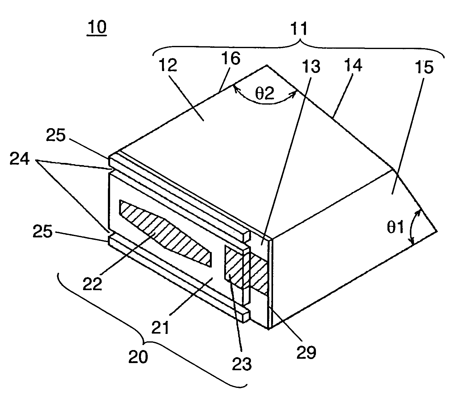
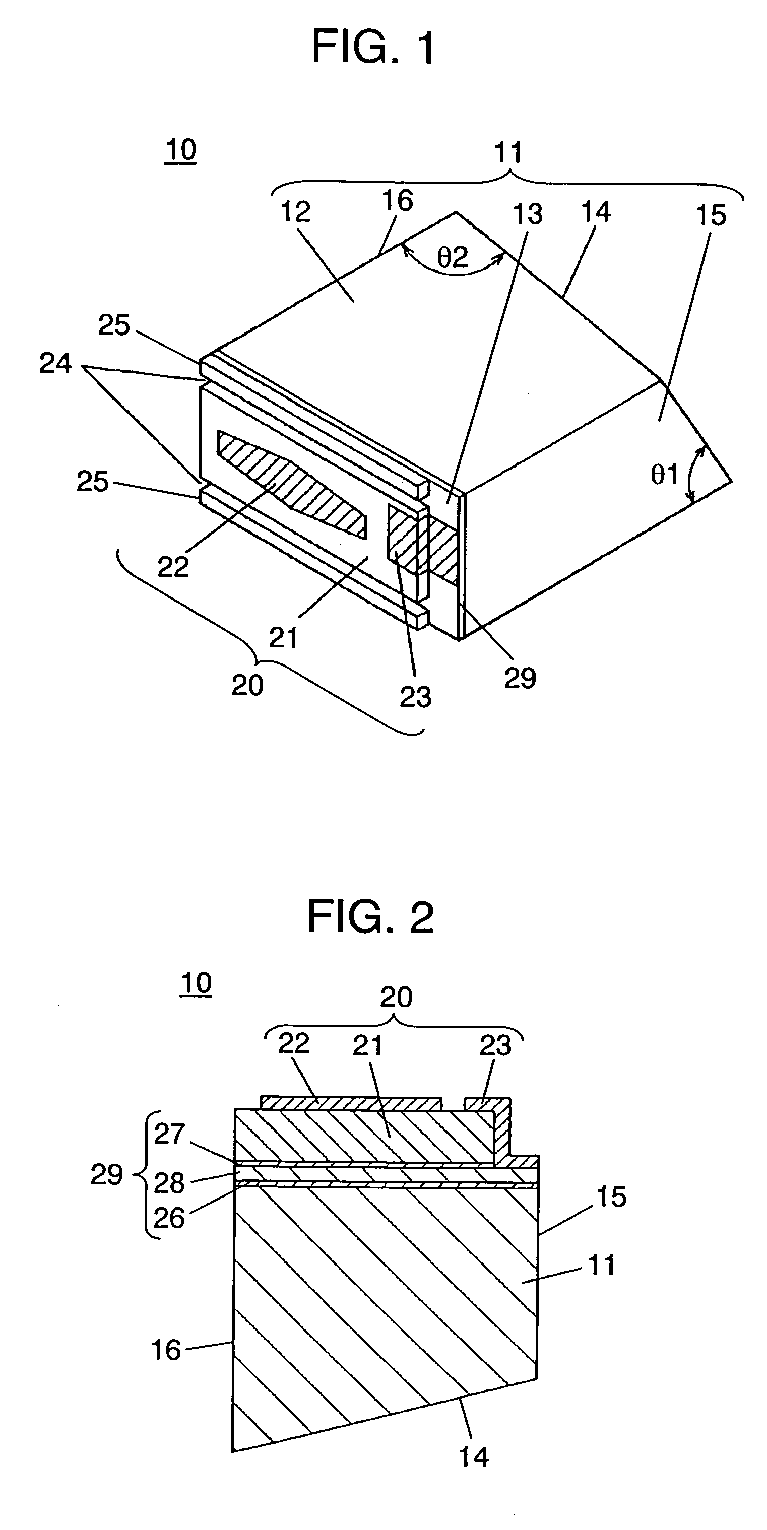
[0029]FIG. 1 is a perspective view of an acousto optic element 10 in accordance with the first exemplary embodiment of the present invention. Acousto optic element 10 in the exemplary embodiment is composed of acousto optic medium 11 and piezoelectric transducer 20 having a piezoelectric characteristic, and is attached to transducer joining plane 13 of acousto optic medium 11.
[0030]Acousto optic medium 11 is an optically transparent material in three-dimensional shape, constituted by transducer joining plane 13 connecting the piezoelectric transducer to the acousto optic medium, inclined plane 14 slantly facing transducer joining plane 13, light incoming plane 15, light outgoing plane 16 facing light incoming plane 15, and two planes surrounded by said planes. One of the two surrounding planes is angle-determining plane 12 determining an angle of inclination of inclined plane 14.
[0031]Inclined plane 14 is two-dimensionally tilted, as is described below, namely inclined plane 14 is tilt
second exemplary embodiment
[0063]FIG. 7 is a perspective view of acousto optic element 40 in accordance with second exemplary embodiment of the present invention. Acousto optic element 40 in the exemplary embodiment is different from the first exemplary embodiment in forming position of groove 42. In acousto optic element 40 in this exemplary embodiment, groove 42 is formed on angle determining plane adjacent to transducer joining plane 13 in multiple numbers centering around an area of front side electrode layer 22 of piezoelectric transducer 20. Groove 42 is formed extended to a part of piezoelectric transducer 20.
[0064]Acousto optic element 40 in this exemplary embodiment is manufactured by a following method. First, bonding piezoelectric transducer 20 to a transducer joining plane of an optical block that will become individual pieces of acousto optic medium 11 later, by an identical method with the first exemplary embodiment. Next, polishing piezoelectric material of piezoelectric transducer 20 and adjustin
third exemplary embodiment
[0070]FIG. 8 is a perspective view of acousto optic element 50 in accordance with third exemplary embodiment of the invention. Acousto optic element 50 in this exemplary embodiment is different from the second exemplary embodiment in a forming position of groove 52. With acousto optic element 50 in this exemplary embodiment, a plurality of grooves are formed on inclined plane 14 of acousto optic medium 11, facing toward a formed area of surface side electrode layer 22 on piezoelectric transducer 20 and making the area its central part.
[0071]Acousto optic element 50 in this exemplary embodiment is manufactured by a following method. First, processing an optical block up to a point connecting front side electrode layer 22 and backside electrode layer 23 to the block, by an identical method with the second exemplary embodiment. Then, cutting the block with a dicing machine along a predetermined cut line and obtaining an individual piece. Next, polishing a plane that will become a inclined
PUM
 Abstract
Description
Claims
Application Information
 - R&D Engineer
- R&D Manager
- IP Professional
- Industry Leading Data Capabilities
- Powerful AI technology
- Patent DNA Extraction
Browse by: Latest US Patents, China's latest patents, Technical Efficacy Thesaurus, Application Domain, Technology Topic.
© 2024 PatSnap. All rights reserved.Legal|Privacy policy|Modern Slavery Act Transparency Statement|Sitemap