Planographic printing plate packaging structure and method for packaging planographic printing plate

a technology packaging structure, which is applied in the field of planographic printing plate packaging structure and method, can solve the problems of increasing becoming a large operational burden, and achieve the effect of reducing the operational burden of users

Inactive Publication Date: 2006-07-04
FUJIFILM CORP +1
View PDF22 Cites 2 Cited by
  • Summary
  • Abstract
  • Description
  • Claims
  • Application Information

AI Technical Summary

Benefits of technology

The present invention provides a way to package and protect planar printing plates without requiring them to be turned upside-down during use. This makes it easier for users to handle these plates and prevents damage from being done due to their shape or movement.

Problems solved by technology

The technical problem addressed in this patent is how to efficiently package and protect planar printing plates while maintain their quality and functionality when they are needed.

Method used


Image

  • Planographic printing plate packaging structure and method for packaging planographic printing plate
  • Planographic printing plate packaging structure and method for packaging planographic printing plate
  • Planographic printing plate packaging structure and method for packaging planographic printing plate

Examples


Embodiment Construction

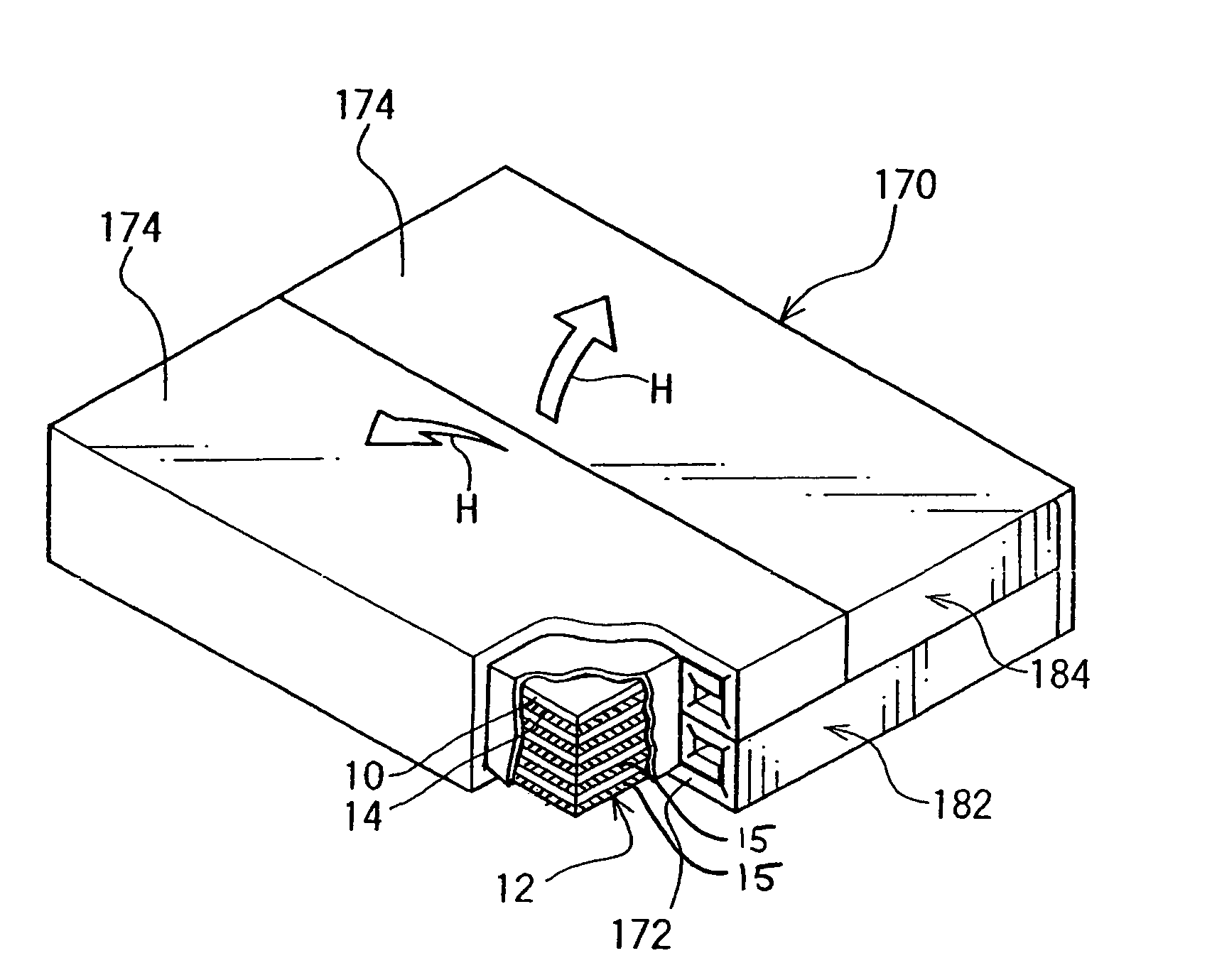
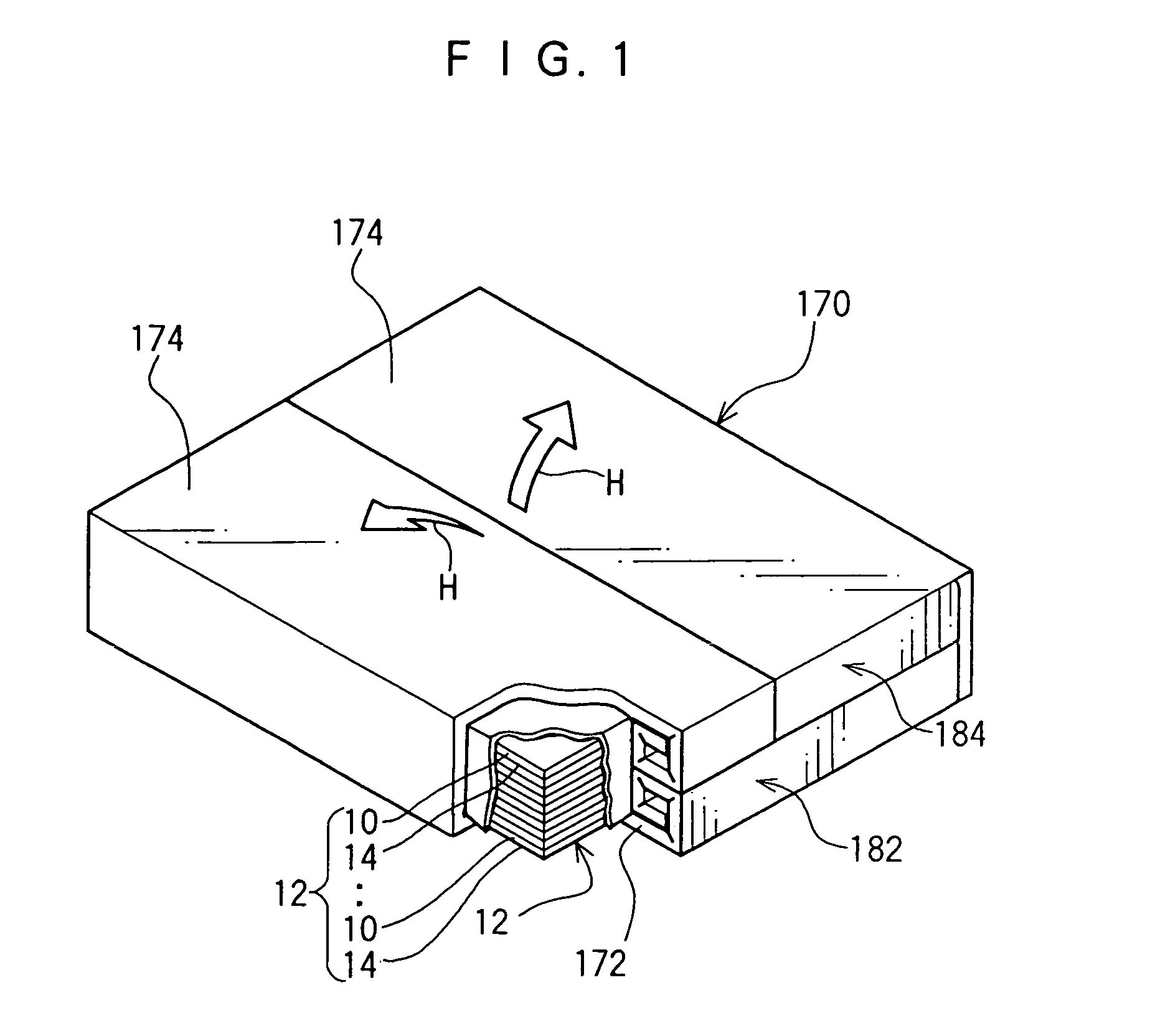
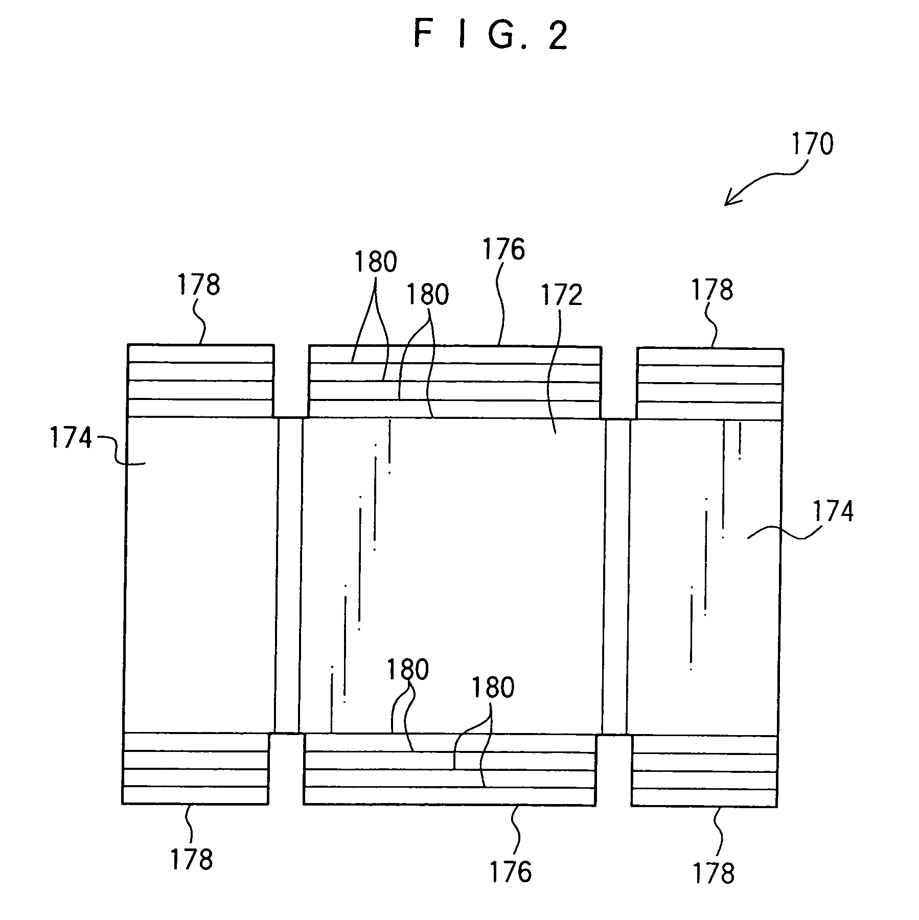
[0031]In FIG. 1, a state (of a planographic printing plate packaging structure), in which a stack 12 of planographic printing plates 10 are accommodated and packaged in a planographic printing plate packaging box 170 relating to an embodiment of the present invention, is illustrated. Also, in FIG. 2, the packaging box 170 for planographic printing plates is illustrated with an unfolded view.

[0032]The planographic printing plate 10 is formed by applying a coating film (a photosensitive layer for a photosensitive printing plate, a heat sensitive layer for a heat sensitive printing plate) onto one surface of a thin aluminum substrate which is in a form of a rectangular plate. This coating film is subjected to a plate making process including exposure, developing treatment, gum coating and the like, set into a printing machine, and coated with ink to print text, image or the like onto a paper surface. Hereinafter, as illustrated in FIG. 3, the substrate surface onto which the coating film


PUM

PropertyMeasurementUnit
Solubility (mass)aaaaaaaaaa

Abstract

A stack of planographic printing plates is accommodated in a packaging box for planographic printing plates in a manner such that imaging surfaces of the planographic printing plates are directed toward a bottom face plate. Therefore, when the packaging box for planographic printing plates is opened in a manner such that top face plates are directed upwards, the imaging surfaces of the planographic printing plates are directed downwards.

Description


Claims


Application Information

Patent Timeline
Owner FUJIFILM CORP
Why Eureka
Try Eureka