Dual-mode converter with linear and comparative feedback modes
- Summary
- Abstract
- Description
- Claims
- Application Information
AI Technical Summary
Benefits of technology
Problems solved by technology
Method used
Image

Examples
Example
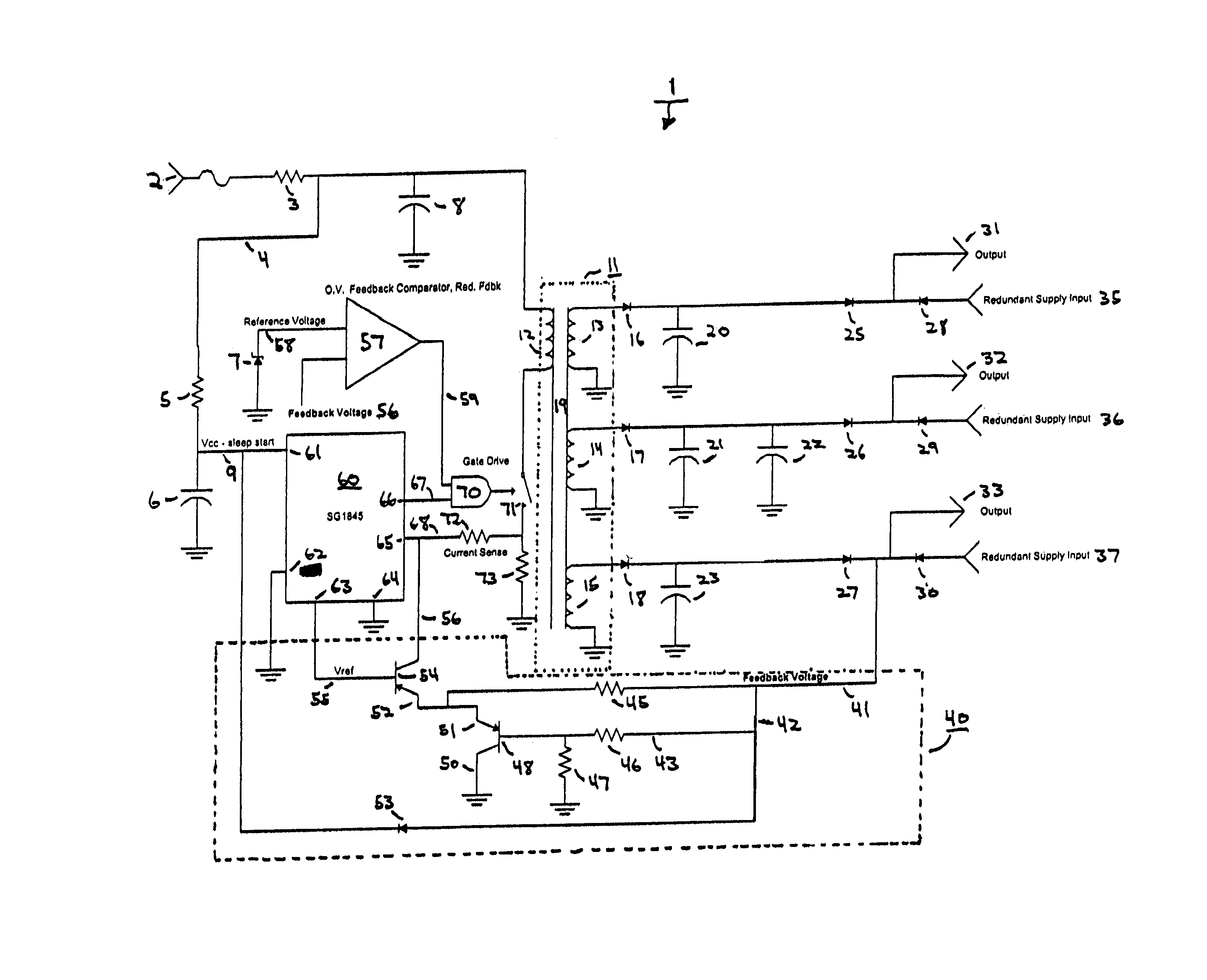
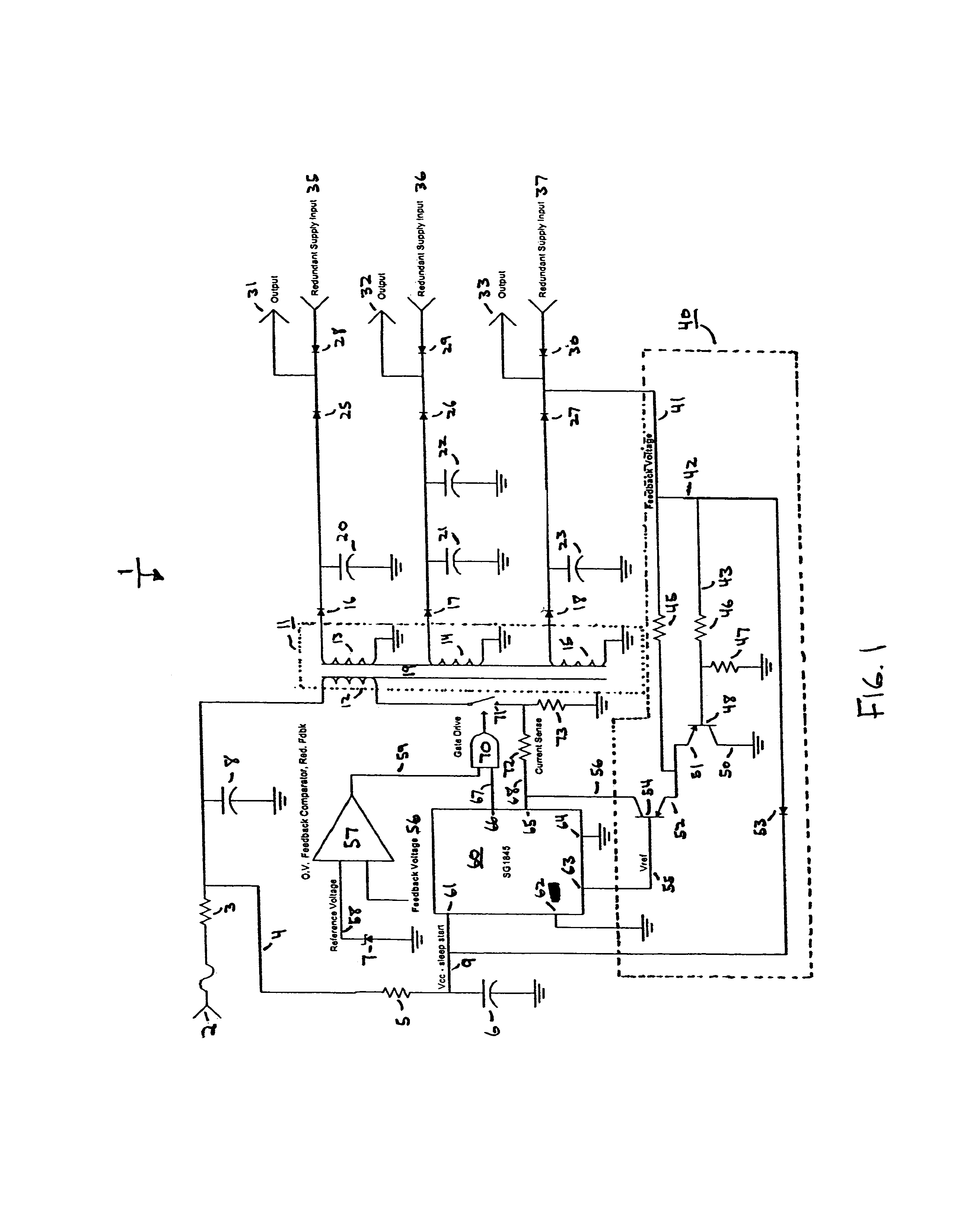
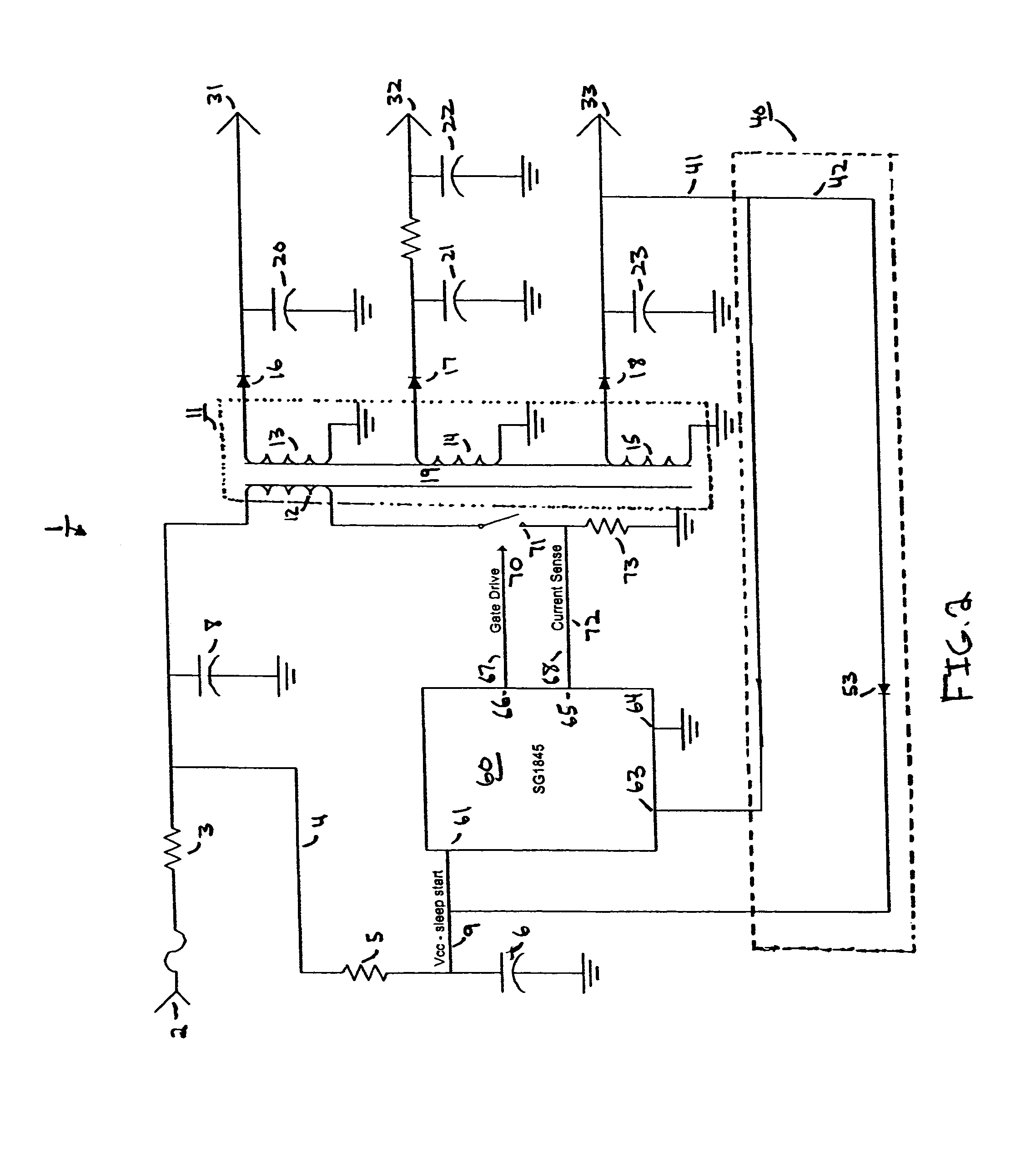
[0018]FIG. 1 shows a schematic of a converter according to one embodiment of the present invention. As seen in FIG. 1, converter 1 includes many common circuit components and is configured to provide a controlled dual-mode converter with a feedback loop that operates in a linear mode under continuous loads, and that operates in a comparative mode under non-continuous step loads.
[0019]Converter 1 receives input signal (load) 2 from a source such as a power supply. Input signal 2 is passed through resistor 3, which is a known type of resistor and may be of a desired resistance to step down the voltage level of input signal 2 to a desired level. Next, input signal 2 is branched to signal 4 which is passed through resistor 5 and split to input signal 9. Also on the path of signal 4 is capacitor 6 for filtering signal 4. The other side of capacitor 6 is grounded. As with resistor 3, resistor 5 and capacitor 6 are known types of components and may be of desired values in different embodiment
PUM
 Abstract
Description
Claims
Application Information
 - R&D Engineer
- R&D Manager
- IP Professional
- Industry Leading Data Capabilities
- Powerful AI technology
- Patent DNA Extraction
Browse by: Latest US Patents, China's latest patents, Technical Efficacy Thesaurus, Application Domain, Technology Topic.
© 2024 PatSnap. All rights reserved.Legal|Privacy policy|Modern Slavery Act Transparency Statement|Sitemap