Method for forming CMOS structure with void-free dielectric film

Inactive Publication Date: 2007-01-16
INTEGRATED DEVICE TECH INC
View PDF12 Cites 5 Cited by
  • Summary
  • Abstract
  • Description
  • Claims
  • Application Information

AI Technical Summary

Benefits of technology

Problems solved by technology

The technical problem addressed in this patent is how to create a void-free dielectric film without any defects during Self-alignment Contact (SCA), which would improve device yields and reduce costs.

Method used


Image

  • Method for forming CMOS structure with void-free dielectric film
  • Method for forming CMOS structure with void-free dielectric film
  • Method for forming CMOS structure with void-free dielectric film

Examples


Embodiment Construction

[0020]Reference will now be made in detail to the preferred embodiments of the invention, examples of which are illustrated in the accompanying drawings. While the invention will be described in conjunction with the preferred embodiments, it will be understood that they are not intended to limit the invention to these embodiments. On the contrary, the invention is intended to cover alternatives, modifications and equivalents, which may be included within the spirit and scope of the invention as defined by the appended claims. Furthermore, in the following detailed description of the present invention, numerous specific details are set forth in order to provide a thorough understanding of the present invention. However, it will be obvious to one of ordinary skill in the art that the present invention may be practiced without these specific details. In other instances, well-known methods, procedures, components, and circuits have not been described in detail so as not to unnecessarily ob


PUM


Abstract

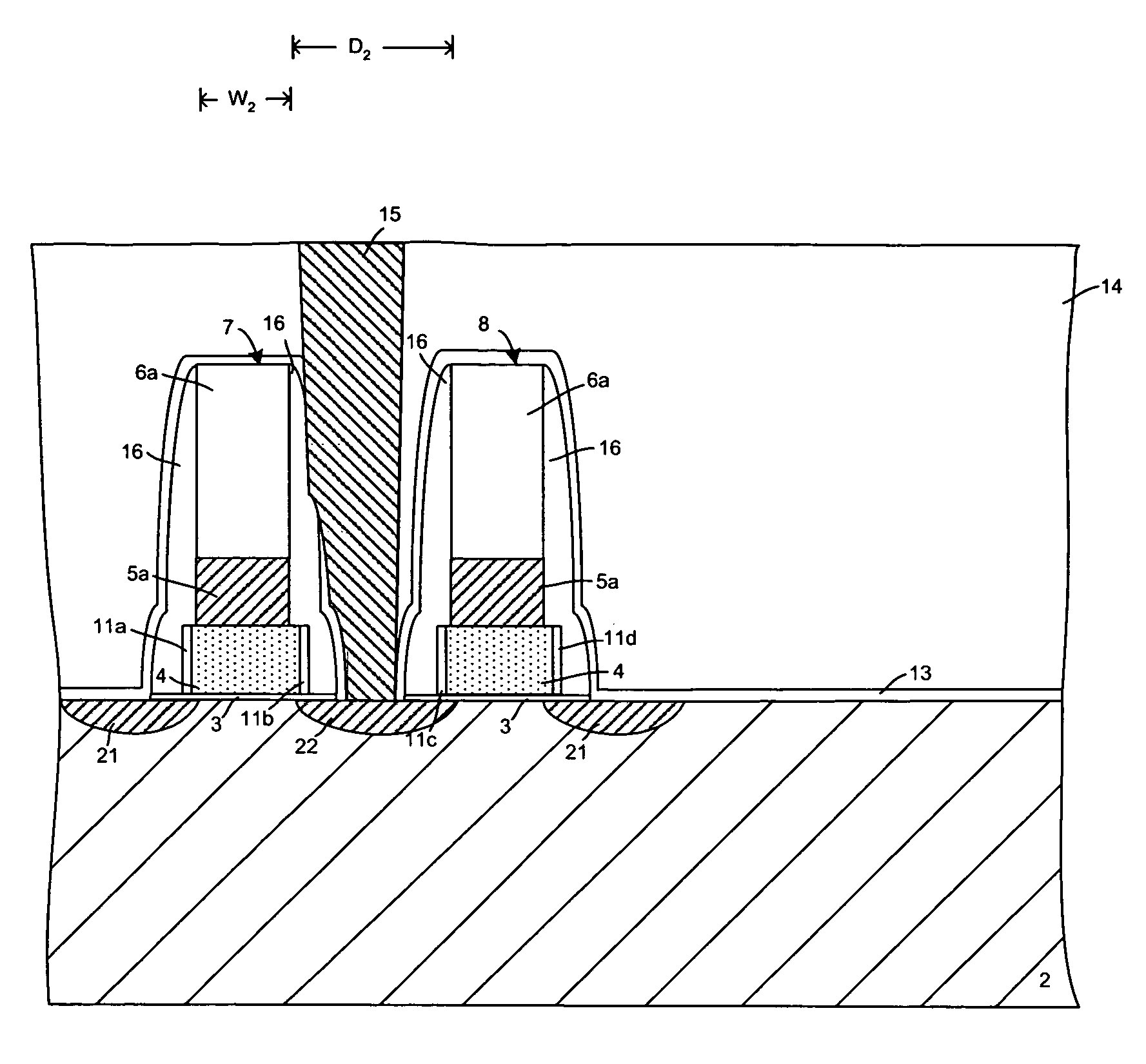
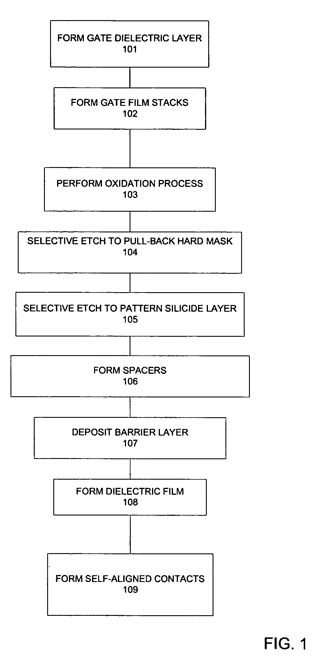
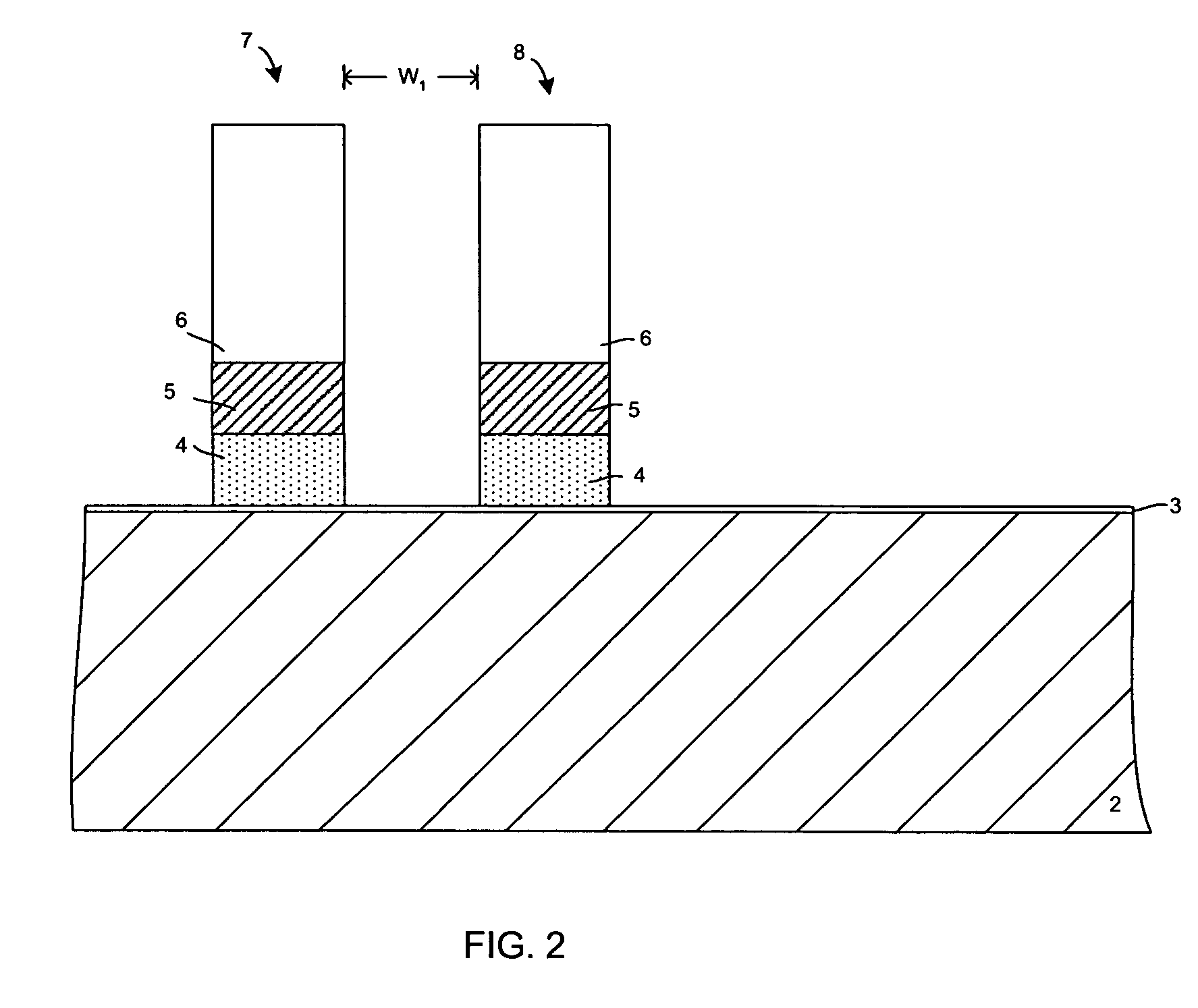
A process for forming a void-free dielectric layer is disclosed in which adjoining gate film stacks are formed on a semiconductor substrate. Each gate film stack includes a silicide layer and a hard mask that overlies the silicide layer. A first selective etch is performed so as to reduce the width of the hard mask on each of the gate film stacks, exposing portions of the top surface of the silicide layer. A second selective etch is then performed to reduce the width of the silicide layer. Spacers are then formed on opposite sides of each of the gate film stacks, and a dielectric film is formed that extends over the gate film stacks. By reducing the width of the hard mask layer and the silicide layer, gate film stacks are obtained that have reduced width near the top of each gate film stack, preventing voids from forming in the dielectric film.

Description


Claims


Application Information

Patent Timeline
Owner INTEGRATED DEVICE TECH INC
Why Eureka
Try Eureka